Conundrum with linking an Nmea 2000 network to a Seatalk ng network

ritchyp

Member
Joined
24 Dec 2022
Messages
116
Visit site
The E90W has a STNG port, connect it to the soon to be spare port on the 5 way connector.

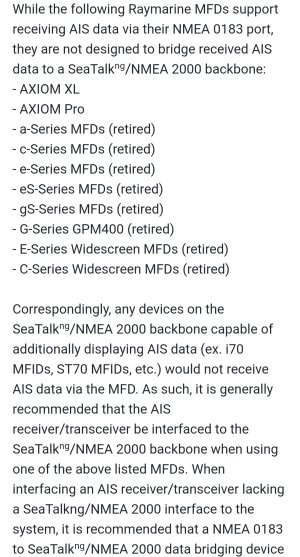
The AIS icon on the E90W will not show that you have AIS unless it's a Raymarine AIS.

The Icom should work fine on 0183. Make sure the wiring is correct and make sure the port on the plotter is set to a baud rate of 38,400

Edit: Typed as Richy was typing #19 :)
Hi Paul,

Thanks for that. This may sound like a stupid question but if the e90W is recieving AIS data for instance on port 2 which is 38400 only, will it show the contacts on the display?

If only Raymarine AIS shows the AIS icon, what would be the point of sending the AIS data to the E90W ? The AIS unit shares the antenna with the VHF radio on the mast head so doesn't need GPS from the E90W.

I can see the data packets coming in by their hundreds of thousands but there are no AIS targets on the Chart Plotter display (E90W)
 

PaulRainbow

Well-known member
Joined
16 May 2016
Messages
17,056
Location
Suffolk
Visit site
Hi Paul,

Thanks for that. This may sound like a stupid question but if the e90W is recieving AIS data for instance on port 2 which is 38400 only, will it show the contacts on the display?
Yes.
If only Raymarine AIS shows the AIS icon, what would be the point of sending the AIS data to the E90W ? The AIS unit shares the antenna with the VHF radio on the mast head so doesn't need GPS from the E90W.
The fact the icon has a X over does not stop it receiving and displaying AIS from your Icom over NMEA 0183
I can see the data packets coming in by their hundreds of thousands but there are no AIS targets on the Chart Plotter display (E90W)
Need to double check your settings.

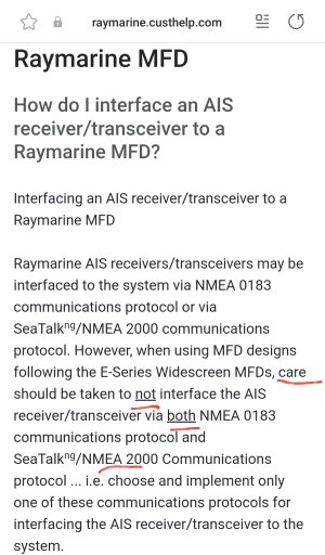
Couple of small points, unless i've missed something and you only need to deal with AIS, for which you are considering a 0183 to N2K converter, i would not waste my money. AIS will work perfectly fine over 0183.

I absolutely would not by the Quark thing, or anything else Quark.
 

ritchyp

Member
Joined
24 Dec 2022
Messages
116
Visit site
Hi,
I spent Friday and Saturday just gone, Fitting the correct backbone adapter cable and therefore successfully joined the N2K network to the STNG network. I removed the red & black power lead going to one of the spurs on the 5 way STNG Back Bone Connector and fitted a black blanking plug which I bought at the Chandlers when I picked up the adapter cable. I have a Garmin GNX20 Wind instrument and a Garmin GND20 which is multifunction but I have set it up to display Depth and STW. It can do other things but I currently don't have a GPS source being fed into this new NME2000 network.
The Old Garmin chart plotter is currently not on any network as I removed the Dataline black box with all the old instruments and the NMEA 0183 cable/connector which is plugged in to it has the other end stripped back to wires and I think I remember that the blue and brown wires were connected to the Dataline black box hub. The separate iCom AIS and VHF are still linked and it shows my position in Lat and Long on both. These 3 devices are mounted on a vertical panel at the back of the chart table. I know I am going to have to buy this Actisense NMea 0183 to 2000 converter in order to get everything linked back up again after removing thr Dataline back box hub.

This my concern though is am I providing enough power to power the the now extended network. I am using the power wire which originally gave power to whole NMEA 0183 network via the Dataline box. The flex has Live and neutral and the individual wires are 1.5mm in diameter. After thinking about the extra power now being drawn by the STNG kit, I figured I should replace the power lead with some 2.5mm diameter flex and remove the old 1.5mm flex. However "Hers's the thing" the Nmea backbone uses a yellow drop cable with a red, a black and a shield drain wire and they are even thinner than the flex that I am using from the old installation. The red wire has an inline fuse so I had a look at the rating and its 3 Amp and looks like a quick blow type as it is not a strand of wire but a metal strip with lines across at intervals.
I decided to power up the instruments and the Autopilot from the isolator switches on the mainboard, when the P70S powered up, it was beeping and displaying a blank screen with a message at the bottom saying No Speed data. I pressed cancel and the display came on showing the heading in standby mode. I decide to test it briefly thinking all was well and engaged the auto pilot and then hit +10 twice and expected it to turn the helm a quarter turn or so but it turned the helm in a series of little jerky movements like it would normal do while holding a steady course but from side to side. It just kept turning clock wise in a series of minute movements and kept going until it has hard over and the rudder was at full turn but it was still trying to turn the wheel so quickly hit standby to stop it.

I don't know what is going with it now. It never beeped and said no speed data before. The power lead for the STNG end of the back Bone is now disconnected but it is now receiving wind data of course. Before this it was in wind vane mode but it couldn't have been getting the data from the old wind transducer as the STNG network was closed.
The last time I calibrated the Autopilot, it moved the helm wheel smoothly and during one part of the process it would turn the helm from full lock to full lock, nice and smoothly without juddering. Something is definitely not right.... I couldn't check it whilst making way under engine because I know have an issue with the engine which will be on a different thread.
 

Martin_J

Well-known member
Joined
19 Apr 2006
Messages
4,405
Location
Portsmouth, UK
Visit site
If all you have done is to command the autopilot to turn by 20 degrees, then it sounds like it is doing what I'd expect.

It would for example try to turn the boat to port with a certain amount of movement. That obviously didn't cause the boat to turn.

With no change in boat heading, the autopilot will then try (in small increments) a number of extra times and then just give up and stop (since it's still not seeing the boat turn).

'No speed data' does seem to imply the autopilot is not seeing speed from the transducer. It will then at some point ignore lack of try speed data and just use configured your configured 'cruise speed' setting.

(You never mentioned calibrating the autopilot this time but just tried it out on +/-20.)

I didn't see any mention of you removing terminators either. Did you remove one from each existing backbone?
 

ritchyp

Member
Joined
24 Dec 2022
Messages
116
Visit site
Yes I did remove one terminator on the end of the STNG back bone. The 5 way connector has one terminator on the extreme end, then there are the 3 spurs ( one was the power for the network) now removed and blanked off. The other end of the 5 way connector has a long backbone cable which is mostly coiled up but enough slack to go to a T connector. That had a spur cable that goes to the pilot controller head and 2 blue terminators. I removed one of them to connect the N2K backbone.

The other extreme end of the N2K backbone has a terminator on the start of the network. There are no spare/unused connections on the N2K network. Where they supplied a terminator for the N2K network, I removed to add the 6 m backbone cable that goes to the stern and via the adapter, it connects to the STNG backbone where I had to remove the one blue terminator so as I understand it. The network is terminated at each far end.
 

ritchyp

Member
Joined
24 Dec 2022
Messages
116
Visit site
Can anybody advise me if they think my source of power & neutral via a pair of 1.5mm diameter cables is sufficient? The fuse is rated at 3Amps and that power comes from the common 12Volt bus on the boats main switch panel.

What's it running?

Via an NMEA 2000 back Bone
The mast head transducer a Garmin GNX Wind
Garmin GND 10 black box bridge
Aimar DST 810 Triducer
Garmin GNX 20 Wind instrument display
Garmin GND 20 Multi-Display

NMEA 2000 linked to Seatalk ng Back Bone
Raymarine EV1 autopilot heading sensor and computer
Raymarine ACU100 pilot drive controller unit STNG power only (not motor drive Voltage)
Raymarine P70s Autopilot controller head and display

Most of the displays are Len 3 so 150 milliamps being drawn

3 Amps would be enough then?

I plan to add my Raymarine E90w MFD & Chartplotter and also link the remains of my old NMEA 0183 to it using an Antisense converter mentioned in one of the posts. There will be a 25 year old Garmin colour chartplotter, an iComm AIS and an iCom DSC-VHF

I bought some 20 amp flex to be able to up the current needed if necessary but the Garmin NMEA 2000 power lead has tiny wires and a 3amp inline fuse so I'm assuming that I would need a beefier power cable with an N2K drop cable end on it to supply power to the 3 linked networks?
 

KompetentKrew

Well-known member
Joined
27 May 2018
Messages
2,439
Visit site
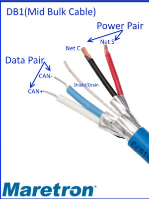
NMEA 2000 / SeaTalkNG have a pair of data wires, a pair of power wires and a shield - the power wires are very thin indeed. I bought several meters of NMEA 2000 cable and a pile of connectors, and I require full daylight to wire them up otherwise I can't see them properly. I have to take photos of the back of the connectors and then zoom in with my phone to see them properly.

So I think you're probably overthinking the power supply requirements.

I have a Raymarine I70s display here next to me, and it says 9V - 18V, 0.25A on the back, so you could run at least a dozen of those with your 3A supply. Your P70s is probably basically the same hardware as the I70, and I bet everything else you list will have comparable current draw. I bet all this kit is designed to run at 9V to allow for voltage loss.

Is it actually working at this stage? You should be able to connect a transducer to a T at the bow end of the NMEA 2000 backbone and an instrument to a T at the stern end; supply power in the middle. Providing it is correctly terminated you should see the data from the transducer on the instrument. That's what you should be checking at each step of building the network.
 

laika

Well-known member
Joined
6 Apr 2011
Messages
8,205
Location
London / Gosport
Visit site
I have it enabled but the icon for AIS and thus to be able to overlay that on the chart display is not active and has a red cross over it

* Is it displaying "NO AIS" and a triangle with a line coming out of it with a red cross or "AIS" and a bell with a red cross over it?
* Do you definitely have "AIS OBJECTS" set to "ON" in presentation->chart layers?
* Are you definitely using the correct output line from the icom (ie the one which outputs AIS)?
 

ritchyp

Member
Joined
24 Dec 2022
Messages
116
Visit site
To answer Kompetant Krew & Laika's most recent posts,

I bought a Garmin pack with all the instruments and transducers, the GND 10 black box bridge which deals with the mast head transducer cable, nexus field installation connector to work natively with N2K and connects to the backbone via a 2m drop cable.
Enough T connectors to have 3 linked together.
One Terminator one end.
3 drop cables for power, to the GND 10 box and one for the Airmar DST810 Speed, temp and depth Triducer.
Also included was a 6m backbone cable to run from the end of 3 linked T connectors.
I ran this to the bridge on the cockpit coming and linked the last two T connectors together and used the supplied 2m drop cables to go to the Wind instrument and the multi display instrument. I had a terminator but removed it after seeing both instrument heads were working ok.

I purchased another 6m backbone cable and installed it on the now vacant end of the two T connectors and routed it to the stern and used a DeviceNet to STNG adapter cable to connect it to my small STNG autopilot network.

If you don't count the length of the cable going up the mast as this goes into the GND Black box bridge and is on a 2m drop cable from the top end of the network. I would say that the network is powered at the top end behind the instrument panel on the chart table.

I disconnected the STNG power cable under the cockpit at the stern and the auto pilot seems to be working. It all powers up and seems to be communicating and the P70S comes on.

I'm afraid I just bought Garmin GNX Wired Sail pack 52 which came with everything you need to create a small Nmea 2000 network and then linked it to my STNG network as the Autopilot had not been getting any Wind data at all as it was a closed network.
Everything appears to be working properly although when I went to go out for calibration of everything, the depth reading was incorrect for a few very scary minutes but it suddenly started displaying a much more realistic depth and continued to do so.

I didn't design my network or calculate voltage drop with Len values. I just linked 2 working network backbones together but had to cut the power at one end as I don't want my autopilot controller and linear drive motor switched on when I only want Wind depth and STW displayed. The instruments and autopilot have there breaker switches labelled on the main panel.
End....

The e90W has a cable that allows it to be used above the chart table or above the helm. At the chart table end the cable is open and besides an optional external GPS antenna socket, there are loads of Choccy blocks with lots of wires connecting to the AiS and VHF radio.
I fully expect that these are sending Nmea 0183 data to e90W. I went through the menu on the iCom MA 500TR AiS to check the baud rate but after going down every sub menu, I could not find it. I assume it can't be set as it will be set to 38400 as standard.

I also have a cooling problem now with my Beta Marine 30 which is on a different thread but that is the priority now as We can't go go sailing safely without a working engine.

When I have sorted that issue this weekend hopefully, I will calibrate all the new kit and before I go anywhere out of sight of land, I will check every wire and replace the cumbersome Choccy blocks with the gel filled telecoms compression connectors and double check my settings on the e90W. I swear I have AIS overlay selected or perhaps attempted to switch it on and got a message saying 'NO AIS'
It has been a long and stressful 6 weeks of work and no Sailing possible and spending £3500 so far. I love to sail but can't really afford it so everything is on credit and on a tight budget.
As I have said before, in the e90W data settings, it says I am receiving many thousands of data packets but I don't have the AIS targets overlayed. Most of the icons on the top right of the screen have little red crosses over them. Autopilot, GPS, AIS, Radar. Touchscreen has no red ❌ as the touchscreen works.

I would like to link the autopilot to the E90W so the pilot can receive Navigation data which it says when you change the P70S from Wind Vane to Track. There is a STng port on the back of the e90W and I do have one spare port on the 5 way STNg backbone connector now, since I disconnected the red and black power cable as instructed.

Will the e90W send any power to the network as if it does, I will need an Isolater cable. Will have to gland another cable through the cockpit floor too.... 🙄

end of answer to Laika. Thanks R
 

Martin_J

Well-known member
Joined
19 Apr 2006
Messages
4,405
Location
Portsmouth, UK
Visit site
The E90W is not capable of powering the SeatalkNG/NMEA2000 backbone..

(The only Raymarine devices that i know of that can power a backbone are their course computers with regulated 12v outputs).

The E90W will though however need to be powered via its own power supply cable ( and the 12v provided on the backbone will just be used to power it's internal SeatalkNG circuitry).

As you say, the power you are providing to the bus is connected more to one end than the other. Installers do suggest locating it towards the middle, but tbh, there are much longer backbones than yours working fine with one power lead at the end so yours should be fine.

Another interesting thing about the wire cores within the backbone and drop leads... When you look at the actual coloured wires, it looks like the blue and white data wires are thicker than the red and black power leads.

Odd you might think.. but on stripping the wires, you'd find the inner cores on the red and black power leads are actually thicker...

The answer lies in the fact the blue and white data pair just has thicker insulations surrounding them.

Screenshot_20230725-173152_Samsung Internet.jpg
 

ritchyp

Member
Joined
24 Dec 2022
Messages
116
Visit site
That's interesting to know Martin.
Yes the e90W has been installed for a fair few years, maybe as much as 10 or more. It has its power and data cable which as I mentioned is double ended for use at the chart table with a bracket there to mount it on. That cable is glanded through the cockpit floor and the other end for use emerges above the chart table so it's good to know that if I put it on the STng network using a a spur cable, it won't be sending any power in to the network. Thanks
 

laika

Well-known member
Joined
6 Apr 2011
Messages
8,205
Location
London / Gosport
Visit site
I fully expect that these are sending Nmea 0183 data to e90W. I went through the menu on the iCom MA 500TR AiS to check the baud rate but after going down every sub menu, I could not find it. I assume it can't be set as it will be set to 38400 as standard.

it says I am receiving many thousands of data packets but I don't have the AIS targets overlayed
Apologies for telling you what you probably already know but according to its manual the icom AIS has 3 outputs and only port 2 output gives AIS: the rest is dsc/gps. If you haven’t checked already might be worth double checking. I don’t think my C90W tells me whats being received: do you definitely see VDM sentences received?
Obviously we’re assuming the icom unit is displaying targets ok.
If yes to all the above the only other setting I can think of to look at is “data master” although, despite never having had more than 1 chart plotter, I thought a direct connection would still work if a master wasn’t available
 

ritchyp

Member
Joined
24 Dec 2022
Messages
116
Visit site
Continued...... I took the boat for a sail last weekend. My main battery is dying. From memory as I will not be able to check until I am back on the boat this weekend, it was 380 or 390 AH. After a day's sailing and a night at anchor on the way back, things were turning off and I checked the battery and it was below 12 volts on the meter. I had to run the engine here and there to stop the Raymarine e90w from turning off.

Later when we were heading up Southampton water, I turned off the the VHF on the switch board. This powered down the VHF radio and the iComm AIS unit mounted next to it. Moments later, the e90w was beeping and showing 'No position' I always assumed that the e90w had built in GPS? The wires that are connected from the AIS and VHF to the double ended loom must be sending the position to the e90w so that is why there is data being received by it. This weekend, I will go through all the manuals and check the wire colours and re connect with gel filled compression joints instead of choccy blocks. Also checking the the baud rate and port number and see if I can get the AIS to display targets on the e90w.

The e90w does have a coax input (where the wiring loom is open) for external GPS I assume? There is a fairly old Garmin chart plotter next to the AIS and this I believe is connected to the Garmin Mushroom on the stern rail. Would I be able to use an antenna splitter and connect this to the e90w antenna input or would that halve the power. There are active splitters that amplify the signal I could use if necessary.

I am sure I saw a thread about a Raymarine E wide series that the internal GPS had stopped working on. I t seem that somebody found a workaround by using the AIS to show the position.

I have a busy weekend ahead of me.......

Anybody know of a supplier of high capacity Lead acid (sealed & maintenance free) batteries. Bolt on terminals all the ones I've seen so far at a quick google are round terminals and not sealed and dont have a very long life warranty on them.

Ritchy
 
Top