Conundrum with linking an Nmea 2000 network to a Seatalk ng network

ritchyp

Member
Joined
24 Dec 2022
Messages
116
Visit site
Hi Members,

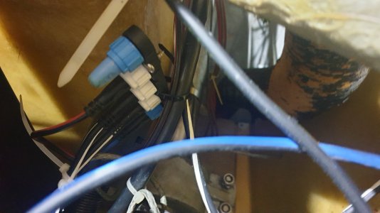
I ran into an issue today after successfully creating a new Garmin based Nmea 2000 network and attempting to join it onto my small Seatalk ng network which is just A Raymarine Autopilot system. P70s Head unit, EV1 heading sensor, AC100 controller and the helm drive motor. This consists of a 5 way back bone connector, a red and black power cable, 2 white and black spur cables going to the EV1 and AC100 and the far end has blue and black back bone cable going to a T connector The opposite end of the T connector has a blue terminator in line and there is one black and white spur lead going up to the P70S controller head unit. Pretty basic really.

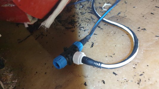
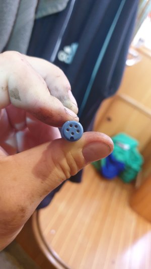
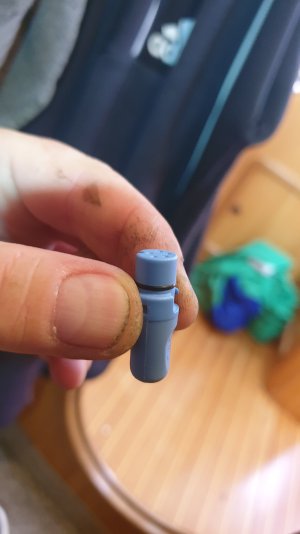
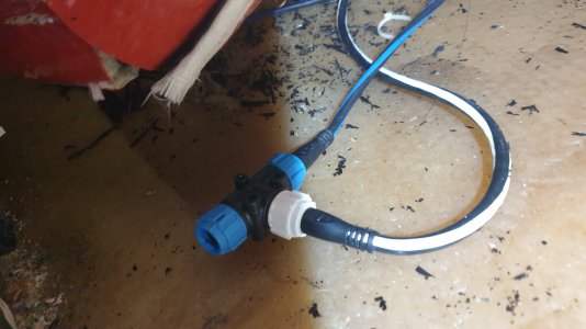
So I have built my NMEA 2000 network. In the Garmin wired sail pack 52, I have all the cables and T connectors and drop cables and terminators to build a working network which works well so far. However, I want to get wind and STW data to the autopilot so I bought and other 6 meter N2K cable to come off of the N2K backbone and run it all the way back to stern to connect to Seatalk ng network. I went to the chandlers and they sold me a small adaptor. Because I am extending the the whole N2K network, it is continuing the back bone down to the stern. I removed the blue coloured back bone terminator from the T piece and attempted to plug in the small adaptor piece. I tried several times without success so Finally I looked at the adaptor end and it had 6 pin holes, I looked at the the end of the T piece (which is the end of the Seatalk ng back bone) and that has only only 5 pins. I then saw and realised that the adaptor piece Force 4 chandlery had sold me was white and black and meant to be inserted into a white spur connector which has 6 pins (I assume that the 6th pin in the centre provides power to the instrument or sensor it connects to.)

So here lies my conundrum! Firstly, I have no available spur sockets to plug into as they are all being used. Secondly, should I not be joining my N2K back bone to my Seatalk ng back bone, there by creating one continuous back bone all the way through the boat. I have power at the Seatalk ng end and power at the start of the N2K network via a yellow drop cable. Each end is terminated properly with the correct terminators.

Have I been sold the wrong adaptor? As it was I had to buy two because I couldn't remember if I need male N2K to female Seatalk ng or the exact opposite. They sold me both and said I could return the one I didn't need.

Surely I would not connect the network together using a 6 pin spur connector? To do that, I would need an additional Seatalk ng back bone cable, another T connector and extend the ST ng back bone so that I had 1 additional white spur connection available, then I could use the adaptor I bought and connect the N2K back bone via the spur connector. Would that work?? It doesn't seem right to me. I don't need more power from the 6th pin......?

I am convinced that I have been sold the wrong type of adaptor. What I want is a 500mm or 1m cable with a male N2K connector on one end and a Seatalk ng female end on the other end. Essentially joining the N2K back bone to the Seatalk ng back bone. I have looked on their website and they do supply them with either male or female Nmea 2000 DeviceNet ends.

Please correct me If I have this wrong. I know they speak exactly the same language but it is only the connectors that are different so I believe that I am just extending or linking the back bones only so I need the Nmea 2000 DeviceNet back bone to Seatalk ng back bone adapter cable and I was unwittingly sold the wrong adaptors (both genders to boot!)

The more I have typed, The more it makes sense now but I would be immensely relieved if one or two or any number of more knowledgeable members than I could verify that I I have now solved the conundrum myself.

Many Thanks Ritchy
 

Attachments

  • 20230717_184301.jpg
    20230717_184301.jpg
    1.1 MB · Views: 9
  • 20230717_184314.jpg
    20230717_184314.jpg
    1.2 MB · Views: 6
  • 20230717_184524.jpg
    20230717_184524.jpg
    832.3 KB · Views: 5
  • 20230717_184539.jpg
    20230717_184539.jpg
    805.4 KB · Views: 4
Last edited:

PaulRainbow

Well-known member
Joined
16 May 2016
Messages
17,050
Location
Suffolk
Visit site
Hi Members,

Have I been sold the wrong adaptor? As it was I had to buy two because I couldn't remember if I need male N2K to female Seatalk ng or the exact opposite. They sold me both and said I could return the one I didn't need.
You do indeed have the wrong cable, you cannot connect the N2K backbone to am STNG spur, it has to connect to the STNG backbone, just like you thought.

Raymarine STNG to NMEA2000 Backbone Adaptor Cable

Note that you should only have a single power supply to the network, so disconnect one or the other.
 
Last edited:

jlavery

Well-known member
Joined
25 Oct 2020
Messages
643
Visit site

PaulRainbow

Well-known member
Joined
16 May 2016
Messages
17,050
Location
Suffolk
Visit site
Agree. However, where does this sit relating to the need for the backbone to be terminated? From OP's post, I fear this requirement has been lost.

@ritchyp - any chance of a network diagram?
The backbone will be correctly terminated. The OP has 2 networks at the moment, a STNG and a N2K, he removes a terminator from the N2K network and one from the STNG network and connects a backbone cable between the 2, it's then just one network.
 

jlavery

Well-known member
Joined
25 Oct 2020
Messages
643
Visit site
The backbone will be correctly terminated. The OP has 2 networks at the moment, a STNG and a N2K, he removes a terminator from the N2K network and one from the STNG network and connects a backbone cable between the 2, it's then just one network.
Doh! Of course. :rolleyes:
 

jlavery

Well-known member
Joined
25 Oct 2020
Messages
643
Visit site
One thing to remember - which I think you have - is that the network should only have one power connection. So if each separate network had power, you'll need to disconnect one of the power lines when you join it.
 

ritchyp

Member
Joined
24 Dec 2022
Messages
116
Visit site
Hi,
Re: Power.

I have a Yellow N2K power cable which joins on to series of 3 T connectors linked together, that is a drop cable. It powers my masthead Wind transducer/anemometer, my Airmar DST 810 Triducer for depth and STW & more. The GND 10 black box interface and finally, the Wind display head and the depth/speed display.
I took the power from a cable that is coming from the main switchboard labeled (Wind, Depth, Speed.)


The Raymarine network needs more current as it powers the heading sensor, the pilot drive controller and the drive motor plus the autopilot controller head unit P70S. This has its own switch on the main switchboard, obviously labeled 'Auto pilot'

Sometimes when we have been out a few days and main house battery is getting low as we haven't been plugged into the mains for a couple of days, I need to conserve power as the battery will need to be replaced before we sail to the med next April/May and I will need a wind generator or solar but for now the battery will suffice while I am crusing and doing sea trials with new equipment and instruments etc. That means that I don't use the auto pilot at all and try not to use too much power while we are under sail when we are heading back to her berth on the last day.

I really don't want to put everything on one power switch. Every boat I have ever owned or sailed has a main switch for autopilot and one for Instruments.

The instruments' power cable is not heavy enough to bridge and run the Raymarine Autopilot's network.
The Autopilot's power would most likely be able to handle the extra load from the Instruments' network but obviously, I don't want to turn on the autopilot to have my depth, windand speed instruments working.

I only want share a d send data around the network and I understand that there is a small amount of current necessary for the data to flow but I really need to keep the two seperate.

How do I achieve this...?

In fact, I want to add my Raymarine MFD/ Chart Plotter to the Raymarine network at some point in the near future but I will need need to use the Seatalk NG port on the back of the device (Raymarine E90W) so there is potentially a 3rd source of power. The blanking plug is white so I'm assuming that it is a spur (6 pin port.) Again that is Isolated and powered by the switch on the main board labeled 'GPS' which runs on anything GPS related including a 20 year old Garmin colour Chartplotter which is flush mounted on a panel above the chart table, next to the VHF radio and AIS unit. Those items are still talking on Nmea 0183 so I'll need add a bi-directional N2K to 0183 converter box but that is not critical at the moment.

I didn't think having the two networks having there own power as always, would matter. I obviously realised that there would be some small current merging at the point where the 2 back bones join but I still want to keep the Isolater switches on the main board as they are.

I feel that I have opened a can of worms now. The Autopilot needs Wind data. Currently it is working in standalone mode and when I am undersail and the wind is faily gusty, the autopilot will lose its heading. On the P70S display, it says Wind vane, currently it is not connected to the MFD which is how the yacht was when I bought it 6 months ago. Track mode is unavailable obviously because it is linked to the MFD so It seems to default to Wind vane mode and in settings you can select true wind or apparent so I was hoping that if it starts getting apparent wind data, it will be able cope in gusty and stronger winds. It's pretty useless as it stands but handy if there isn't much wind or none at all so You motor or motor sail.

I need advice on this power source issue and how to deal with it, Without having one switch does all!
Networking the E90W will need to done via the main cable which has a connector at the chart table and one above the binnacle where I keep it mounted. The cable is open near the other end and quite a few wires connected to the Nmea output on the AIS and also an external antenna socket but it is currently using the built in one.

I could keep going for hours but my main concern is the advice about disconnecting one of the power sources which wouldn't work safely and wouldn't work for me either.

There must be a solution, which is why I have taken my time to carefully explain everything clearly I hope.

For those asking for wiring diagram, I think that if you read the context of the Thread and some of the comments from other contributors, I don't feel it is really necessary I think the issue at stake here now is the power source/s.

I have now order the correct back bone to back bone adaptor cable which I will have by Friday so I can make the connection and make my cabin back into a cabin as it is currently all engine, transmission and a battery the size of a small suitcase.

A heartfelt solution is now what I am hoping to get from this thread now.

Signing off......Thanks Ritchy
 

Martin_J

Well-known member
Joined
19 Apr 2006
Messages
4,403
Location
Portsmouth, UK
Visit site
Two quick thoughts on that..

The autopilot computer does not take it's power from the small SeatalkNG backbone that you have.. It does as you say need the higher current in order to drive the linear drive.

The SeatalkNG backbone will have it's own power supply. It's not the case auth the ACU-100, but a lot of the larger Raymarine autopilot computers have a switch whereby they 'can' provide 12v to the backbone if needed.

I would expect therefore for your short SeatalkNG backbone to have it's own power supplied via a (from memory) 5A fuse.


You've not mentioned which wind MHU you have.

Some of the wind MHUs are NMEA2000 and (due to max drop cable limitations) have a built in 120 ohm terminator (and for that the backbone extends right up the mast)..
Others don't, and they have a convertor box at the base of the mast to provide the NMEA2000 connection.
 

Martin_J

Well-known member
Joined
19 Apr 2006
Messages
4,403
Location
Portsmouth, UK
Visit site
You do need ascertain if the Wind MHU is on the backbone (and incorporates a termination resistor) because this will determine where you place the other termination resistor (or resistors).

Having too many termination resistors can be as bad for the signal as not having enough.

One way to check afterwards would be to find a spare drop cable and strip to bare wires. Power down the backbone and connect the stripped drop cable. Using a multimeter, measure the resistance between the blue and the white (signal wires).

Going by the formula for resistors in parallel (which is what you effectively get when you put a resistor across the blue/white at any location on the bus.

1689690012352.png

you will get a total measured resistance between white/blue of 60ohm if there are two 120 ohm terminators correctly in place.

If you find the resistance measures 120ohm then you've only got one terminator on the backbone.
If you find the resistance measures 40ohm or even 30ohm then you're likely to have either three or four terminating resistors (respectively) on the backbone.

The Tx circuit in each device is designed to see a 60ohm resistance. Anything more or less can give rise to errors.
 
Last edited:

ritchyp

Member
Joined
24 Dec 2022
Messages
116
Visit site
Hi Paul,

I bought the pack as a self contained kit from Garmin. It containes everything needed to create a closed N2K network. The masthead unit has a proprietary connector at the mast head and I had to wire up (with a colour coded pin out diagram) another proprietary 4 pin connector which plugs into the Nexus port on the included and supplied GND10 interface box see link please

Garmin GND 10 Interface Box

With one male and one female terminator at each end of the network, the GNX 20 wind instrument was working perfectly and after putting the Airmar DST 810 triducer into its through Hull housing, the depth and speed GND 20 instrument was also giving me depth and I turned the paddle before I inserted it and I was getting speed too.

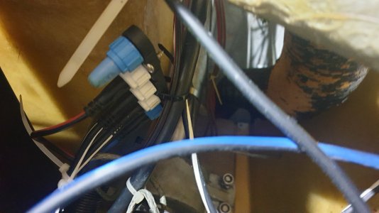
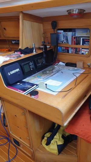
Every part of the Garmin N2K network was working perfectly. As I said, so I could get wind data to the Raymarine autopilot, I removed the terminator from the end of the network behind the instrument console in the cockpit bridged across the top of hatchway and then ran a 6m deviceNet cable from the the back bone where the terminator had been down through the aft double cabin and in to the stern void under the cockpit and attempted to plug the cable in by removing the terminator shown in the photograph on the OP but found that it was a spur adapter so I had to stop and leave the boat as it was due to it being late evening and I had to drive back home to go to work today. I have bought the correct cable now . If you click on the 2nd photograph, you can see the 5 way STNG 5 way terminal and a red and black power cable is plugged into one of the spur ports.

Cheers Richy
 

Attachments

  • 20230717_184301.jpg
    20230717_184301.jpg
    1.1 MB · Views: 5
  • 20230717_184314.jpg
    20230717_184314.jpg
    1.2 MB · Views: 5

Martin_J

Well-known member
Joined
19 Apr 2006
Messages
4,403
Location
Portsmouth, UK
Visit site
I didn't think having the two networks having there own power as always, would matter. I obviously realised that there would be some small current merging at the point where the 2 back bones join but I still want to keep the Isolater switches on the main board as they are.

One way your current setup might be is that the 'autopilot' breaker powers up the ACU and the small Seatalk NG backbone (via both a thick pair to the ACU and a thinner pair to the SeatalkNG power input cable.. Hence a reason why switching on one isolator might power up both ACU, P70 and the Seatalk NG backbone.

As you say, your smaller 'instruments' isolator is likely providing power to the smaller plotters and the NMEA2000 backbone.

If the above are both true, you really need to unpower the SeatalkNG backbone when you interconnect the two backbones (because it will get power from the NMEA2000.


This is another reason for having a spare drop cable with a stripped end (and perhaps the ends put into a chocolate block).. You can then put a multimeter across the red/black and see exactly which isolators provide power to the backbone.
 

Martin_J

Well-known member
Joined
19 Apr 2006
Messages
4,403
Location
Portsmouth, UK
Visit site
Posted too late.. your post #10 does indeed show the Seatalk NG power cable (that can be removed when the backbones are connected).

It would still be nice to find out which isolator that actually gets it's power from though!!

As to the GND10.. yes, that is just an end system on a drop cable.. It's the B&G type wind MHUs where the backbone is taken to the masthead and they therefore need the bus terminator to be built into the MHU itself.

Good luck with the interconnect - TBH - you could have cut a SeatalkNG cable, cut an NMEA2000 cable and joined red-red, black-black, white-white and blue-blue.. (I'm not really suggesting that!)

BTW- the 'extra' pin you found on some of the Raymarine cables is the old 'Seatalk 1' yellow wire for backward compatibility if you still have some old instruments around.
 

PaulRainbow

Well-known member
Joined
16 May 2016
Messages
17,050
Location
Suffolk
Visit site
Hi Paul,

I bought the pack as a self contained kit from Garmin. It containes everything needed to create a closed N2K network. The masthead unit has a proprietary connector at the mast head and I had to wire up (with a colour coded pin out diagram) another proprietary 4 pin connector which plugs into the Nexus port on the included and supplied GND10 interface box see link please

Garmin GND 10 Interface Box

With one male and one female terminator at each end of the network, the GNX 20 wind instrument was working perfectly and after putting the Airmar DST 810 triducer into its through Hull housing, the depth and speed GND 20 instrument was also giving me depth and I turned the paddle before I inserted it and I was getting speed too.

Every part of the Garmin N2K network was working perfectly. As I said, so I could get wind data to the Raymarine autopilot, I removed the terminator from the end of the network behind the instrument console in the cockpit bridged across the top of hatchway and then ran a 6m deviceNet cable from the the back bone where the terminator had been down through the aft double cabin and in to the stern void under the cockpit and attempted to plug the cable in by removing the terminator shown in the photograph on the OP but found that it was a spur adapter so I had to stop and leave the boat as it was due to it being late evening and I had to drive back home to go to work today. I have bought the correct cable now . If you click on the 2nd photograph, you can see the 5 way STNG 5 way terminal and a red and black power cable is plugged into one of the spur ports.

Cheers Richy
You connect the backbone as i said previously (how you though so yourself. But, you do need to disconnect one of the power cables, doesn't matter which, although the way it switches on might dictate which works best.

Anything that needs a heavy current, such as the autopilot, will have it's own power supply. The N2K.STNG network will only power low current devices, such as transducers and some small displays.

Personally, i would disconnect both power cables, put one in a safe place, this will free up either, a N2K or a STNG socket. Connect the remaining power cable to a switch supply of its own.

Martin has also posted lots of useful info here too.
 

ritchyp

Member
Joined
24 Dec 2022
Messages
116
Visit site
Re your helpful comments Martin.

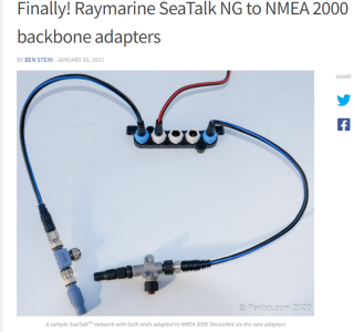
So having already purchased a cable, one of which is on the left hand side of your photo (mine is DeviceNet male to STNG female)
All I need to do, Is unplug the red and black spur cable because it is only supplying the small amount of current necessary to move the data around and provide power to the P70S and EV1.
As you say, with that red/black cable removed, that current will be supplied by the N2K network now.
So the ACU 100 and the linear drive motor are getting thier power from a separate higher ampage power cable coming from the Isolater switch on the main distribution board.
I can still turn my instruments on from their own isolator switch and the working/grunt end of the autopilot will be switched off when not needed to reduce power consumption.

That's all good news indeed. This also now gives me one free spur port on the 5 way. Maybe I can get a rudder angle sensor and I should imagine that would only need a spur cable to power it and send the data to the ACU 100.

If I have taken all this in correctly please give me a thumbs up

Thanks, Richy
 

Martin_J

Well-known member
Joined
19 Apr 2006
Messages
4,403
Location
Portsmouth, UK
Visit site
Perfect..

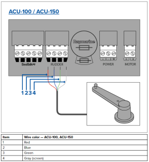
Apart from the fact you will not need that spare backbone port for a rudder sensor (see diagram).. But I am fairly certain that within a few years you'll have another 5-way SeatalkNG connector block in the backbone and at least half a dozen more NMEA2000 T-pieces!!!

1689694939791.png
 

ritchyp

Member
Joined
24 Dec 2022
Messages
116
Visit site
Perfect Martin, you have solved my conundrum for now thank you.

One question for the future though. This Raymarine E90W MFD is still working as a standalone unit and I want to get more information from the other instruments on it.
As I mentioned, the loom has a lot of wires connected to Choccy blocks and the Nmea output from the older icom AIS MA 500 TR.
The e90W is definitely receiving plenty of data packets on the Nmea 0183 port but it is not showing AIS and I have it enabled but the icon for AIS and thus to be able to overlay that on the chart display is not active and has a red cross over it as is the Autopilot but we know that is not on the remains of the 0183 network after I pulled out the old Dataline black box and removed all the old Stowe instruments that had failed or were working intermittently.

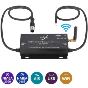
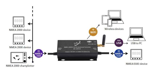
I think I will have to get the Quark QK-A032 Bidirectional Nmea 2000 to 0183 gateway with USB and WiFi.
Very reasonable at £128

Perhaps I will have more luck getting data from the linked N2K and STng network if I convert it to 0183.

I would like to have the AIS overlay working as It is permanently showing collision alert on the display at the chart table and almost as soon as you clear it, it repeats the same thing but that's because I'm sailing in the Solent a lot as the boat is up near the docks in Southhampton.

I forgot to mention, I have a digital yacht WL510 and inavconnect long range wireless router and the e90W dows have a SThs port on the back too so I could tap into that but at some point when I have more cash, I need to get a digital HD radar scanner which uses all that SThs connectability.

I have options but for now want to get the AIS and Autopilot working with the MFD.

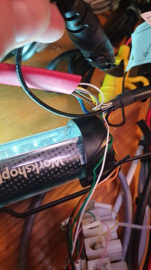
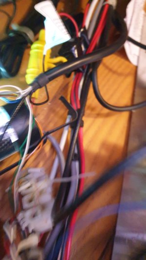
The photo of the wiring loom is the open part of e90W loom. I'm afraid you cant see all the choccy block connectors but I intend to remove them all and rewire again with the gel filled compression couplers that the telephone and cable engineers use now to tidy it all up and make sure everything is connected properly and the right wires are connected.

Signing off....Ritchy
 

Attachments

  • 20230319_120513.jpg
    20230319_120513.jpg
    1.3 MB · Views: 5
  • 20230508_161319.jpg
    20230508_161319.jpg
    1.5 MB · Views: 5
  • 20230508_161323.jpg
    20230508_161323.jpg
    1.2 MB · Views: 3
  • A032AIS-1000x1000.jpg
    A032AIS-1000x1000.jpg
    70 KB · Views: 3
  • A032-diagram1100x550-1.jpg
    A032-diagram1100x550-1.jpg
    122.8 KB · Views: 4
Last edited:

Martin_J

Well-known member
Joined
19 Apr 2006
Messages
4,403
Location
Portsmouth, UK
Visit site
The Actisense would be one way of putting the AIS data onto the backbone (and thus be visible on all displays).

The AIS unit should however be able to send it's AIS data to the E90W using NNEA0183. It's not really related to this thread but I'd be checking the wiring and that the baud rate is set to 38400 for receive on the E90W. (Although it unusual that the AIS unit can actually be set to transmit at either 4800 or 38400 on ports 1 and 3. Looking at the manual though, the second MA-500tr port is fixed to output at 38400bps).

AIS GPS also needs to have found it's position in order for the AIS to output data onto NMEA0183.
 

ritchyp

Member
Joined
24 Dec 2022
Messages
116
Visit site
Hi Martin,

One last question and then I'll go and get on with it all on Friday.

If I want the E90W and the autopilot to talk to each other so that that the autopilot can make course changes on a plotted route. Would running a STng spur cable down to that spare spur socket I am going to have, work?
I'm fairly certain it's a spur connection on the back of the e90W because the blanking plug is white...

Ritchy out (y)
 

PaulRainbow

Well-known member
Joined
16 May 2016
Messages
17,050
Location
Suffolk
Visit site
The E90W has a STNG port, connect it to the soon to be spare port on the 5 way connector.

The AIS icon on the E90W will not show that you have AIS unless it's a Raymarine AIS.

The Icom should work fine on 0183. Make sure the wiring is correct and make sure the port on the plotter is set to a baud rate of 38,400

Edit: Typed as Richy was typing #19 :)
 
Top