meb
New Member
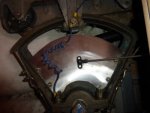
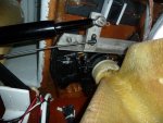
I have a 1987 Beneteau First 405 and wish to fit a Raymarine EV 200 autopilot with a ST1 linear pack to steer the boat. Fixing the linear drive direct to the rudder stock would be the strongest connection and give independence from the wheel steering system. The rudder stock square section top protrudes through sole boards in the cockpit locker but needs to allow the emergency tiller to slide over it. The rudder quadrant is fixed by two bolts nipping together a slotted hub which grips the rudder stock. Connecting a fabricated lever to the two bolts would mean the linear drive motor would interfere with the sole boards.
There is little room under the quadrant and the top rudder stock bearing and it is not clear what is the shape of the rudder post at that point. if it is square then maybe a lever with a similar hole through it could be slid down after taking off the quadrant. Assuming the rudder does not fall off.
The last option would be to buy or fabricate two plates to sandwich say 3 spokes of the quadrant to spread the stresses and bolt through. This latter would probably mean fitting the linear drive upside down.
Has anyone managed to fit such a linear drive and can you please tell me how it was done? Or other suggestions welcome.
Thanks
Mike