Busbars again and daisychaining two fused switch panels?

steve yates

Well-Known Member
Joined
16 Oct 2014
Messages
4,113
Location
Benfleet, Essex/Keswick, Cumbria
Visit site
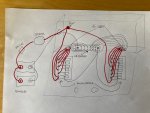
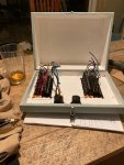
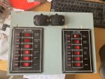
Sorry to keep asking questions about this, I'm almost there but I want to be very clear in my mind what I'm about before I actually do it. My lastpost on electrics was whether I needed busbars or not with my set up of switch panels, it convinced me I want them to keep the wiring secure and tidy, especially when the fuse box lid is opened. As you can see from the pic,there are 2 panels in the lid of my fusebox, with 6 switches each. Thats handy as it gives me a individual switch for every single load.

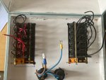
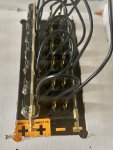
I think I want a positve bus bar and a negative busbar, mounted in the back or base of the box. (pic of the attachments at back of switch panels attached)


Q1) Will two of these do the trick? 100Amp BusBar 2 M6 Studs 12 M4 Screws Terminals with Cover Kit Bus Bars Ground Distribution Blocks: Amazon.co.uk: Sports & Outdoors

Or are smaller ones and just attach a couple of wires to each screw, but if so would I lose both devices if a fuse blows on one switch? I don't think I do , but want to be sure.

I understand that I basically bring the wires from all my various devices into the box, and run the pos wire for each one to a separate screw in the pos busbar, and run the neg wire of each device to the corresponding screw on the neg bus bar. Then I take a short length from each pos screw to the pos connection at the relevant fuse in the panel, and repeat the same with a short length from each neg busbar screw to the neg connection at the relevant switch in the panel.( Currently there is a short length of pigtail on these neg connections which I just remove and chuck.)

My pos battery cable will come into the box and attach to a stud on the pos bus bar, a neg battery cable will run from a stud on the neg bus bar back to the battery.

What I don't have clear is exactly how the busbars and the switch panels are connected.

So Q2) is, should I run two lengths of pos battery cable from the other stud on the pos busbar, one to each switch panel? And then the same with 2 lengths of neg battery cable attached to the other stud on the neg busbar, with one cable to the neg connection on each switch panel?

This is how I think it should go, but someone mentioned dasiychaining the two switch panels together, is that an alternative method and how exactly would I do that, if my idea above is incorrect?

Or in fact, as long as there is a cable from batt to pos busbar and another from neg busbar back to batt, will that suffice as all the individual device wires between the busbars and switch panels will make the circuit as they are switched on? This is actually where I have been confusing myself I think.

And lastly, q3) I say battery cable between the busbars and switch panel, but if I do need a large capacity cable between switch panel and busbar, does it have to be? The busbars are rated at 100a, can I use slimmer cable between busbars and switch panels as long as it is rated above the total current likely from all 6 switches at once? Thinking of bulkiness and space in the box when closed.

Thanks
 

Attachments

  • bethfran-fusebox-2.jpg
    bethfran-fusebox-2.jpg
    110.9 KB · Views: 52
Last edited:
I am sure you are still confused about bus bars vs terminal blocks

Bus bars link all the connections together ......... that what you can use for your negative connections ( you could double up the connections and use a shorter bus bar though if more convenient)

All the positive connections from your various devices will need to come in to separate terminals on a terminal block .... it'll be no good if they are all connected together on a bus bar!
Then from each terminal you will need a connection loop to the respective switch and fuse on the hinged front.

Cannot see without a decent photograph of the switch and fuse layout how you will need connect a common positve supply to all the switches. A positive bus bar maybe, unless they are already all linked

( if there are indicator lights on the switch panels , or illuminated switches , you will also need a negative supply for them

The positve wiring needs to be rated for the max current it will carry. ( heay wire for the comm on incoming connection to the switch panels .. lighter wiring for the individual circuits)
The negative for panel lights will only need to ne quite light as it will only carry the current which the lights take

Post a decent photograph of the back of the individual switch panels

You need to get somebody to draw you a proper wiring layout diagram once they can see what the layout of the individual switch panels is . Its hopeless trying to describe wiring in words.
 
Last edited:
Yes your right, I have been hearing busbars/terminal blocks used interchangeably, but they seem to do different things.
So really my questions should be.... what do I use to take the pos feeds from my devices, and then link each feed to the switch panel, and what do I use to take the meg feeds for each device and then link to each switch?
And how best do I attach the pos and the neg battery cables and to what inside the fuse box, and then make them connect to the switch panels?

I had been intending in the original to use one each of the bus bars, one for pos and one for neg, but actually it seems like I should have one busbar and one terminal block?
Battery pos to a busbar, to make the connections to the pos side of the switch panels, and a terminal block to receive the neg wires from the devices, then perhaps cable the negative bars on the switch panels to a post, and attach the battery neg to that?

Will post better pics tomorrow. I will draw a new diagram for comment, once I grasp how to join it all up. It's the physical connecting of the switch panels to everything else via some kind of intermediary that I'm struggling to understand.
 
Referring to the positive and negative bus bars on your switch panels as described in the instruction leaflet you posted recently this is roughly how I think you will have to wire things ... I show the 12 way bus bar from your link above for all the negative connections

I show two 6 way terminal blocks for the positive connections but if you can find a single 12 way one you can use that if you prefer

You will only need to connect negatives to the switch panels if the switches are illuminated


1615781474531.png
 
Last edited:
Thanks a lot vic, thats really helpful.
So what exactly is that I install at top right? A post with two studs?
I have attached some clearer pics, though think you have pretty much clarified it for me.
( just for clarity, I realise my 12v sockets will connect directly to the switch and wont require a busbar screw ir terminal block connection)
 

Attachments

  • AE0DBE72-4757-494F-9655-9788BC98A5E2.jpeg
    AE0DBE72-4757-494F-9655-9788BC98A5E2.jpeg
    97.5 KB · Views: 23
  • BF5AE6FE-D131-4002-A9ED-27C423A4792D.jpeg
    BF5AE6FE-D131-4002-A9ED-27C423A4792D.jpeg
    126.3 KB · Views: 78
  • D60BC89B-E425-4C3B-83EF-0486E818F029.jpeg
    D60BC89B-E425-4C3B-83EF-0486E818F029.jpeg
    103 KB · Views: 24
The other consideration is that a positive busbar can have fuses or circuit breakers attached in order to run large loads, such as an inverter or anchor winch. The main switch panel is generally kept for smaller loads.

There are some commercial alternatives such as the Victron unit below, but you can make your own with ANL or Mega fuses directly connecting to the busbar.

7061154F-1263-4416-BEB1-4878EC70ED55.jpeg
 
I was thinking perhaps a power distribution post for the battery positive connection ( bttery positive connection will of cousr be via a main fuse and the battery isolator)
1615801255051.pngor 1615801419754.png

Ok I understand that you intend to omit the positive terminal blocks and connect directly to the switches. Personally Id use the terminal blocks terminating all incoming wiring on the fixed half of the box

If you had a fixed front panel with an opening rear access that would be better and also put the negative bus bar ( or two shorter ones ) on the front panel and the positive power terminal post there too
 
No, I will use the terminal blocks you suggested, and as you suggested, the images just show what I have set up so far. I had stopped because I wasn't sure about the busbar/blocks issue and what to use.
The box is actually fixed at the rear with a drop opening front, the front opening is where the switch panels are, so I will attach the post, busbar & terminal blocks to the rear or the side of the box.
So something like this is where I’m at now.
 

Attachments

  • 258E736B-9918-433E-BFD2-4FA85B07E746.jpeg
    258E736B-9918-433E-BFD2-4FA85B07E746.jpeg
    904.9 KB · Views: 24
Last edited:
I originally had an isolator and 1 120a/hr battery, but I have built a new battery box cum companionway seat and have room for two batteries, so I'll probably have a 1-2-off switch instead of an isolator. I know all the arguments but for the moment I have an old one spare, and its just a wee boat with no inboard or engine starting required, I'll use the fancier vsr ideas when I get round to rewiring the big boat :)
What sort of loads would attach directly to the battery, rather than via the switch box. I'm thinking the little circular voltmeter display, to keep an eye on them? An auto bilge pump with float switch if I ever installed such a thing? And a solar controller when I install the panel? Anything else that would bypass a switch panel?
 
Last edited:
Looks over complicated to me.

Using a power post needs care with fusing. If you used, say, 10mm cable to the post and then took two cables off to the panel busbars you would have to fit two more fuses, or continue with 10mm cable. Or, you could use 10mm cable to the post (for voltage drop mostly) and then 6mm cable to the busbars, with a single fuse at the source end, rated for the 6mm cable, at the most.

You will only have 6 positive wires and one negative from each panel, hardly thick looks that won't bend when you close the front.
 
Some of my last post went missing somehow.

I see no value in the terminal block. Why not just connect the equipment wires straight to the switches ?

A) Make short cables to come from the switches, to the terminal block and then connect the equipment to the terminal block.

B) Connect the equipment to the switch.

B is less work and less connections (even if you have to extend some/all of the existing wiring). Doesn't matter which way you do it, the wiring from the switch panels to the back of the box will need to be designed so there is enough length to reach the switches, whilst neatly bending to fold into the box when the front is closed, an easy task either way.
 
I originally had an isolator and 1 120a/hr battery, but I have built a new battery box cum companionway seat and have room for two batteries, so I'll probably have a 1-2-off switch instead of an isolator. I know all the arguments but for the moment I have an old one spare, and its just a wee boat with no inboard or engine starting required, I'll use the fancier vsr ideas when I get round to rewiring the big boat :)
What sort of loads would attach directly to the battery, rather than via the switch box. I'm thinking the little circular voltmeter display, to keep an eye on them? An auto bilge pump with float switch if I ever installed such a thing? And a solar controller when I install the panel? Anything else that would bypass a switch panel?
You dont need all those separate negative wires from the negative bus bar to the switch panels. Just one to each .. Its only for the switch illumination

The positive spade terminals on the switch panels will limit the total power you can take from each

Dont like your panels very much
 
As I suggested in the other thread, because there is space between the switch/fuse panels, why not attach the terminal block and neg. bus bar on the lid? Any wire that might be stressed by bending (when opening the lid) would be better terminated by ring and screw rather than by a spade IMO.
Something like this?
IMG_2615.jpg
 
I had a similar Taiwan switch paned but mine came with wiring nd only needed to be connecter to one incoming power one negative for the indicator lights and one wire for each device connection as Vic suggested.

I take it yours came without any wiring
 
no, they came wired as you see them

Ok now I can see the input power common strip (bus bar) and the negative common strip (bus bar)

several ways to wire the up. I used crimp bullet connectors ensuring the female bullet is on the supply site to the bus bar and on the output wire of the switches.

As in Baba Yaga's diagram

You could also use terminal blocks those with a pressure leaf spring. (so the screw does not clamp the wire directly.

I use din rail terminals mainly as its east to add connector and to supply more than one device like cabin lights /12 V power outlets.
 
You dont need all those separate negative wires from the negative bus bar to the switch panels. Just one to each .. Its only for the switch illumination

The positive spade terminals on the switch panels will limit the total power you can take from each

Dont like your panels very much
Ah, ok. So I can run two cables from the other post on the neg busbar, one to each panel?

Some of my last post went missing somehow.

I see no value in the terminal block. Why not just connect the equipment wires straight to the switches ?

A) Make short cables to come from the switches, to the terminal block and then connect the equipment to the terminal block.

B) Connect the equipment to the switch.

B is less work and less connections (even if you have to extend some/all of the existing wiring). Doesn't matter which way you do it, the wiring from the switch panels to the back of the box will need to be designed so there is enough length to reach the switches, whilst neatly bending to fold into the box when the front is closed, an easy task either way.

More than one way to skin these cats it seems :) Ok, I like the idea of simplifying, just need to think about the wire movement vs the confined space etc, and make a call on terminal blocks or none.

As I suggested in the other thread, because there is space between the switch/fuse panels, why not attach the terminal block and neg. bus bar on the lid? Any wire that might be stressed by bending (when opening the lid) would be better terminated by ring and screw rather than by a spade IMO.
Something like this?
View attachment 111327
Yes I like the idea of the security of a ring and a screw, a lot! But as Paul suggests, I may be overthinking what should be a very simple installation.
I'm not sure how I would join the two panels on your diagram, they only have one spade connection point each per pos and neg. So if the battery pos comes into one, there is no separate lug to take another connection across to the second panel, if you see what I mean from the pics?
 
Ah, ok. So I can run two cables from the other post on the neg busbar, one to each panel?

Yes, the negatives on the switch panel are only for illumination and have busbars, same as the fuses.

More than one way to skin these cats it seems :) Ok, I like the idea of simplifying, just need to think about the wire movement vs the confined space etc, and make a call on terminal blocks or none.

Indeed, there is more than one way and on bigger/more complex boats/installations i'd likely suggest something different, starting with ditching the switch panels :) But, i'm aware of the boat and it's simplicity, so see no point in going over the top.

As for cable flexing, it's a moot point. Doesn't matter if you run the 7 wires straight to the equipment or to a terminal block, it's still 7 wires from the panel to the box, that simply need to be long enough to drop the front. Cable tie them together into a loom, with a curve in it, so it just bends when you put the front on. It's not as though the front is going up and down every 2 seconds, once screwed in place it'll probably not see the light of day for years.
 
Ok, thanks everyone, I think I have a plan now. I'm going to take pauls suggestion of leaving out the terminal connectors for the moment, and if when I set it all up, I not happy with the wiring direct to the opening door, I'll stick a couple of blocks in at the back and connect the loads to them instead then loop them over.

The rest of it is as Vic, Paul and Baba suggested. Here is the latest incarnation...
 

Attachments

  • 84970378-0643-4BDC-98F2-D939C8B2C51F.jpeg
    84970378-0643-4BDC-98F2-D939C8B2C51F.jpeg
    944.6 KB · Views: 19
Top