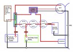
BEP VSR wiring

pvb

Well-known member
Joined
16 May 2001
Messages
45,590
Location
UK East Coast
Visit site
So you are using an emergency switch to disconnect the "both" strap, so allowing the engine start bank to be continuously switched on without it draining to the house side?

That's how I understand it. The standard system, as shown in your picture, is as poorly conceived as the 1-2-Both switch, in that it requires manual intervention.

And then the vsr to direct the charge both separately but at the same time according to need? So if you put the alternator charge to the vsr, then two feeds from the vsr to the load side of the isolators, with the strap cut by your switch, the vsr should sense which bank needs the charge and routes it accordingly.

That's not how VSRs work. The alternator charges one battery; when that battery reaches a certain voltage, the VSR links the batteries together so that they both charge. When the charge voltage is removed, the VSR disconnects the batteries.

If I have finally got my head around it, you have proved that the vsr isnt sensing and routing the charge correctly, you however have proved you can do it manually by closing the strap switch? Uf so, go back a few posts and your vsr aint working properly?
Stu

Maybe, but it may just be incorrectly wired.
 

davidej

Well-known member
Joined
17 Nov 2004
Messages
6,685
Location
West Mersea. north Essex
Visit site
So you are using an emergency switch to disconnect the "both" strap, so allowing the engine start bank to be continuously switched on without it draining to the house side? And then the vsr to direct the charge both separately but at the same time according to need? So if you put the alternator charge to the vsr, then two feeds from the vsr to the load side of the isolators, with the strap cut by your switch, the vsr should sense which bank needs the charge and routes it accordingly. If you need to have both banks on together then close the strap switch? If I have finally got my head around it, you have proved that the vsr isnt sensing and routing the charge correctly, you however have proved you can do it manually by closing the strap switch? Uf so, go back a few posts and your vsr aint working properly?
Stu

I think everything except your last sentence is correct.

The reason why I say this is that when the motor is started:

1. Th red light comes on indicating that it has sensed the raised voltage

2. If I then disconnect the red from the house battery, it shows a voltage to earth of about 14

I will go with new heavier leads and cleaning connections

I crimped the battery end tags on myself but will get the new ones done professionally with a decent crimper.

If that doesnt work......
 

brman

Member
Joined
5 Jul 2017
Messages
147
Location
Hampshire
Visit site
I am assuming the instructions are the same as these..http://www.jgtech.com/pdf/VSR_instructions.pdf
And it is wired as per the 2nd page?
Left or right diagram?

Silly question, but I assume the led comes on when the engine is running?
Edit. Ignore, I see you just answered this.
Btw if you are worried about the cable size measure the voltage at both ends of each cable, on the terminal stud. Any significant difference will show you have a problem with the cable size of terminal crimps. Measuring on the core itself (you can normally get to them from the ring side of the crimp) will tell you if the voltage drop is across the cable out the crimp.
 

davidej

Well-known member
Joined
17 Nov 2004
Messages
6,685
Location
West Mersea. north Essex
Visit site
I am assuming the instructions are the same as these..http://www.jgtech.com/pdf/VSR_instructions.pdf
And it is wired as per the 2nd page?
Left or right diagram?

Silly question, but I assume the led comes on when the engine is running?

At the risk of repeating myself, I first wired it as the lhs diag, then realising that i had a dual sensed, i changed to the rhs.

Since I sail with both the isolators for the house and motor batteries closed, it shold be no surprise that it makes bu**er all difference.
 

PaulRainbow

Well-known member
Joined
16 May 2016
Messages
17,904
Location
Suffolk
Visit site
At the risk of repeating myself, I first wired it as the lhs diag, then realising that i had a dual sensed, i changed to the rhs.

Since I sail with both the isolators for the house and motor batteries closed, it shold be no surprise that it makes bu**er all difference.

It will make no difference to alternator charging whether it is dual sensed or not. Having it dual sensed will mean that if the engine battery will get a top up from the solar panel.

IMO you need to take some voltage readings, thus ;

With the engine not running ;
At the house bank directly.
At the house connection on the VSR

With then engine running ;
At the alternator.
At the engine connection to the VSR.
At the house connection to the VSR.
At the house batteries.
 

Heckler

Active member
Joined
24 Feb 2003
Messages
15,817
Visit site
I think everything except your last sentence is correct.

The reason why I say this is that when the motor is started:

1. Th red light comes on indicating that it has sensed the raised voltage

2. If I then disconnect the red from the house battery, it shows a voltage to earth of about 14

I will go with new heavier leads and cleaning connections

I crimped the battery end tags on myself but will get the new ones done professionally with a decent crimper.

If that doesnt work......
I dont think cable size has anything to do with this, a red herring. A seriously bad connection perhaps but I still have doubts about the vsr as well. The prob with measuring with a digital voltmeter is that a bad connection will show as good voltage but put a load on and it goes tits up. Similarly with the circuits in the vsr. It is telling that closing that strap connection alllows full charge to both banks!
Stu
 

davidej

Well-known member
Joined
17 Nov 2004
Messages
6,685
Location
West Mersea. north Essex
Visit site
I dont think cable size has anything to do with this, a red herring. A seriously bad connection perhaps but I still have doubts about the vsr as well. The prob with measuring with a digital voltmeter is that a bad connection will show as good voltage but put a load on and it goes tits up. Similarly with the circuits in the vsr. It is telling that closing that strap connection alllows full charge to both banks!
Stu

That makes good sense.

As i said, i crimped the battery end tags on myself with a cheap tool and they don't look too good. They could easily be where the bad connections are.

For a few quid, i could gt professionally made ones.
 

brman

Member
Joined
5 Jul 2017
Messages
147
Location
Hampshire
Visit site
At the risk of repeating myself, I first wired it as the lhs diag, then realising that i had a dual sensed, i changed to the rhs.

Since I sail with both the isolators for the house and motor batteries closed, it shold be no surprise that it makes bu**er all difference.

Sorry, not easy to keep up on my tablet. In which case I would do the measurements Paulrainbow and I mentioned. If they don't show a problem then I would suspect a dodgy get.
 

VicS

Well-known member
Joined
13 Jul 2002
Messages
48,606
Visit site
davidej;6171084[COLOR="#FF0000" said:
]At the risk of repeating myself, I first wired it as the lhs diag, then realising that i had a dual sensed, i changed to the rhs.[/COLOR]

Since I sail with both the isolators for the house and motor batteries closed, it shold be no surprise that it makes bu**er all difference.

Despite several request for a link to the wiring instructions you followed it is only now and only thanks to brman that we have that link!

The first obvious question is, Do you have a 710-125A (SINGLE SENSE) VSR or do you really have the 710-125A-DS (DUAL SENSE) VSR?

You have so far kept its identity secret despite requests to identify it

You ain't going to get the former to work as a dual sense VSR . You need the latter! 710-125A-DS
Can you now confirm once and for all the exact model of VSR you have.
 

pvb

Well-known member
Joined
16 May 2001
Messages
45,590
Location
UK East Coast
Visit site
Despite several request for a link to the wiring instructions you followed it is only now and only thanks to brman that we have that link!

The first obvious question is, Do you have a 710-125A (SINGLE SENSE) VSR or do you really have the 710-125A-DS (DUAL SENSE) VSR?

You have so far kept its identity secret despite requests to identify it

You ain't going to get the former to work as a dual sense VSR . You need the latter! 710-125A-DS
Can you now confirm once and for all the exact model of VSR you have.

In post 33, the OP said "It is definitely a BEP 710 - 140 amp - it says so on the back."

He also said that the instructions were written in 2007. Back in 2007, BEP only made the 125A VSR. The 140A DVSR (digital) was introduced in 2013.
 

PaulRainbow

Well-known member
Joined
16 May 2016
Messages
17,904
Location
Suffolk
Visit site
I dont think cable size has anything to do with this, a red herring. A seriously bad connection perhaps but I still have doubts about the vsr as well. The prob with measuring with a digital voltmeter is that a bad connection will show as good voltage but put a load on and it goes tits up. Similarly with the circuits in the vsr. It is telling that closing that strap connection alllows full charge to both banks!
Stu

Not as helpful as you might think Stu, closing the emergency switch bypasses the VSR and it's wiring.
 

PaulRainbow

Well-known member
Joined
16 May 2016
Messages
17,904
Location
Suffolk
Visit site
Although it would be nice to know what the OP has, it isn't going to make any difference whether he has the DVSR, a single or dual sensing 710, as far as his problem is concerned.
 

brman

Member
Joined
5 Jul 2017
Messages
147
Location
Hampshire
Visit site
I know, point I was making, it works without it
Stu

A good point, Which points to what Paul was saying saying. It must either be the cabling to the vsr if the vsr itself that is causing the voltage drop. That should be easy enough to determine by measuring the voltages carefully when under load (ie charging from the alternator).
 

davidej

Well-known member
Joined
17 Nov 2004
Messages
6,685
Location
West Mersea. north Essex
Visit site
With the help of the latest helpful advice I think I have got to the bottom of the problem.

I took the back off the VSR so I could get to the terminals. I then starter the motor and measured voltage between each of the connections from battery to battery.

The only significant drop was across the VSR itself - about 1.5V.

I then disconnected one of the battery connections and measured the resistance across the VSR when it was allegedly closed- about 180 ohm.

So it is the VSR not the connections. Top marks to Stu - thanks mate! It was the point about digital volmeters not giving sensible teadings until a load is applied that got me to the correct conclusion.

Until I can fit a new one I am back to fiddling with the engine isolator every time I start and stop the motor.

PS I dont know why people thought i was being secretive about the model. I said any number of times it is a BEP 140 amp - I didn't know that there is a later digital version until someone posted a link to it.

So thanks to all who contributed. Lets draw this monster thread to a close!
 
Last edited:

PaulRainbow

Well-known member
Joined
16 May 2016
Messages
17,904
Location
Suffolk
Visit site
With the help of the latest helpful advice I think I have got to the bottom of the problem.

I took the back off the VSR so I could get to the terminals. I then starter the motor and measured voltage between eack of the Connections from battery to battery.

At last :)

The only significant drop was across the VSR itself - about 1.6V.

I then disconnected one of the battery connections and measured the resistance across the VSR when it was allegedly closed- about 180 ohm.

That's bad.

So it is the VSR not the connections. Top marks to Stu - thanks mate!

Please, don't encourage him. :)

While you are fitting the new VSR get those dodgy looking cables replaced with nicely crimped ones, as fat as is sensible.

Until I can fit a new one I am back to fiddling with the engine isolator every time I start and stop the motor.

Demonstrates how well the system works and how the added switch gives you a failsafe in more ways than one.
 

BabaYaga

Well-known member
Joined
19 Dec 2008
Messages
2,495
Location
Sweden
Visit site
Until I can fit a new one I am back to fiddling with the engine isolator every time I start and stop the motor.

And before replacing like for like, perhaps give some thought to other options?
This below is just a humble suggestion for a set up that will normally not expose the relay to any large currents (which may or may not have been the cause to the failure of the VSR).
simplified wiring diagram BabaYaga.jpg
 

pvb

Well-known member
Joined
16 May 2001
Messages
45,590
Location
UK East Coast
Visit site
This below is just a humble suggestion for a set up that will normally not expose the relay to any large currents (which may or may not have been the cause to the failure of the VSR).

Can't see that this layout would reduce the current handled by a VSR or combining relay.
 
Top