ColinR
Well-Known Member
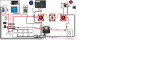
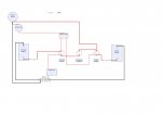
I was trying to track down a problem with the VSR on my BEP battery management the other day which led me to having a closer look at the way charging and battery separation is setup. The charging wire goes from the alternator to the house batteries, so they start charging first and the VSR connects the starting battery when the voltage reaches 12.8v so it charges as well. Wouldn’t it be better for the alternator wire to go to the start battery to charge it first? The VSR sense wire is shown going to the start battery connection in the installation diagram. I asked BEP about that and they said it doesn’t matter which battery it goes to as its dual sensing. Don’t get that.
Having the alternator wire connected to the house batteries means that there is a connection from the house battery to the alternator and then from the alternator to the starter motor even when the battery switches are off. I discovered that with the positive leads disconnected from both house and start batteries, it was still possible to press the start button and it would engage the starter motor. The only way it could get power was back down the alternator wire. Is this normal? I didn’t let it turn over like this, just pressed the button momentarily and it engaged.
Any insights welcome!
")

")