Alternator exciter circuit lamp parallel resistor, what size?

vas

Well-known member
Joined
21 Jun 2011
Messages
7,926
Location
Volos-Athens
Visit site
Paul explained the logic in his first post.
if you're 12V you would need a smaller R. What value did you use btw? get a 50 and a 100 and try them (but get BIG BUGGER resistors not the typical 1/4W tiny ones, or if you use them for a test, make sure you don't let the bulb on for more than 10-15secs...
Definitely one end of the resistor on the one cable where the bulb fits, the other on the other side.
I have a somewhat empirical knowledge of electrics, cannot explain (nor have the time to try to elaborate right now I'm afraid)

cheers

V.
 

DHV90

Member
Joined
23 Aug 2013
Messages
325
Visit site
Paul explained the logic in his first post.
if you're 12V you would need a smaller R. What value did you use btw? get a 50 and a 100 and try them (but get BIG BUGGER resistors not the typical 1/4W tiny ones, or if you use them for a test, make sure you don't let the bulb on for more than 10-15secs...
Definitely one end of the resistor on the one cable where the bulb fits, the other on the other side.
I have a somewhat empirical knowledge of electrics, cannot explain (nor have the time to try to elaborate right now I'm afraid)

cheers

V.


I've used a 50 ohm big ceramic resistor on the 12v side and 150 ohm on the 24v side both rated for up to 50w. I understand the logic well up until the parallel circuit part, I thought that current would follow the path of least resistance so struggling with why a parallel circuit is needed. Im comfortable with using a resistor as a current draw, but cant get my head around how it works in parallel and why it needs to be parallel rather than in series with the warning bulb?
 

RichardS

N/A
Joined
5 Nov 2009
Messages
29,236
Location
Home UK Midlands / Boat Croatia
Visit site
The resistance of two resistors in parallel is less that the resistance of either. Is this the issue?

If you put two 2 ohm resistors in parallel, the total resistance is 1 ohm so the current is not really following the path of least resistance in the literal sense.

I don't know if that helps?

Richard
 

VicS

Well-known member
Joined
13 Jul 2002
Messages
48,235
Visit site
Thanks Vic, i understand those things, the bulb in question is a filament bulb but a tiny one that runs on a fraction of a watt, not an LED but not enough to excite the alternator (from what I understand)

Im just confused about why the resistor needs to be in parallel to the small filament bulb rather than in series

Im going to try a bigger filament bulb over the next few days to simplify matters, but would like to understand whats happening a bit more rather than avoiding it as it might help in the future.

Ig nore the references to LEDs... getting two threads muddled up

A very low power bulb will not pass enough current t to excite the alternator.
You can overcome this by increasing the power of the warning light or by adding a resistor ( about 50 ohms for 12 volt system) in parallel with the bulb. Then you get the very small current flowing through the bulb plus the current flowing through the resistor.
Consider it like the small flow of water that gets through a lock on a river The bulb) plus the larger flow that goes over the weir ( the resistor)

( in order to get the same current on a 24 volt system a 100 ohm resistor should be about right)
 

DHV90

Member
Joined
23 Aug 2013
Messages
325
Visit site
That will work, bare in mind they give off a little heat.
The resistance of two resistors in parallel is less that the resistance of either. Is this the issue?

If you put two 2 ohm resistors in parallel, the total resistance is 1 ohm so the current is not really following the path of least resistance in the literal sense.

I don't know if that helps?

Richard

Hi Richard, in that scenario with equal value resistors both sides are the path of least resistance, im curious of what happens when unmatched resistors are in parallel, and how much the current is split between them.


Ig nore the references to LEDs... getting two threads muddled up

A very low power bulb will not pass enough current t to excite the alternator.
You can overcome this by increasing the power of the warning light or by adding a resistor ( about 50 ohms for 12 volt system) in parallel with the bulb. Then you get the very small current flowing through the bulb plus the current flowing through the resistor.
Consider it like the small flow of water that gets through a lock on a river The bulb) plus the larger flow that goes over the weir ( the resistor)

( in order to get the same current on a 24 volt system a 100 ohm resistor should be about right)

Hi Vic, again, Im quite happy with all of that as has been explained before, I just dont understand why the resistor has to be in parallel rather than in series. Surely a 100 ohm resistor in series with the lamp would have the same effect of increasing the flow to the field coils.
 

VicS

Well-known member
Joined
13 Jul 2002
Messages
48,235
Visit site
Hi Richard, in that scenario with equal value resistors both sides are the path of least resistance, im curious of what happens when unmatched resistors are in parallel, and how much the current is split between them.

Hi Vic, again, Im quite happy with all of that as has been explained before, I just dont understand why the resistor has to be in parallel rather than in series. Surely a 100 ohm resistor in series with the lamp would have the same effect of increasing the flow to the field coils.

No it would decrease it !
 

RichardS

N/A
Joined
5 Nov 2009
Messages
29,236
Location
Home UK Midlands / Boat Croatia
Visit site
Hi Richard, in that scenario with equal value resistors both sides are the path of least resistance, im curious of what happens when unmatched resistors are in parallel, and how much the current is split between them.
If the resistances are unequal and in parallel, then the total resistance seen by the voltage is less than the smallest of the individual resistors so the total current flow is increased but is split across the resistances in proportion to their resistance. Each resistance therefore passes a higher current than it would if it were connected on its own.

Richard
 

VicS

Well-known member
Joined
13 Jul 2002
Messages
48,235
Visit site
Hi Richard, in that scenario with equal value resistors both sides are the path of least resistance, im curious of what happens when unmatched resistors are in parallel, and how much the current is split between them.

Richard seems to be Off line at the moment so I'll answer

The current (I) flowing through a resistor is inversely proportional to its resistance (R). I ∝ 1/R

This means that if you have two resistors in parallel one of which has 3 times the resistance of the other the current flowing through the higher resistance one will be 1/3 of the current flowing through the other'

For example:
A 1.2 watt 12 volt bulb, which has a resistance of 120 ohms, and a 40 ohm resistance in parallel connected to a 12 volts supply

The current through the bulb will be 12 ÷ 120 = 0.1 amps

The current through the resistor will be 12 ÷ 40 = 0.3 amps

This shows how a resistor in parallel with a small bulb increases the total current. The total current flow through the pair will be 0.4 amps

You can calculate the combined resistance of two or more resistors in parallel from the formula 1/R = 1/r1 + 1/r2 +1/r3 etc where R is the combined resistance and r1, r2 etc are the values of the individual resistances
 

VicS

Well-known member
Joined
13 Jul 2002
Messages
48,235
Visit site
I thought that I had answered the question at 21:40 .... although your worked example may be helpful.

Richard
Youve said something at 21: 40 that is not right

You said "Each resistance therefore passes a higher current than it would if it were connected on its own. "
The whole point is that if there are two or more resistors in parallel each one will still pass the same current is it would on its own.
 

RichardS

N/A
Joined
5 Nov 2009
Messages
29,236
Location
Home UK Midlands / Boat Croatia
Visit site
Youve said something at 21: 40 that is not right

You said "Each resistance therefore passes a higher current than it would if it were connected on its own. "
The whole point is that if there are two or more resistors in parallel each one will still pass the same current is it would on its own.
Ah yes .... poor phrasing on my part. Short but not quite so sweet. ;)

Richard
 

TernVI

Well-known member
Joined
8 Jul 2020
Messages
5,070
Visit site
Hi Richard, in that scenario with equal value resistors both sides are the path of least resistance, im curious of what happens when unmatched resistors are in parallel, and how much the current is split between them.

..
V=IR.
So, I=V/R

Two resistors in parallel, add up the current in the two resistors, as the voltage is the same
Itotal= (V/R1) + (V/R2)

It follows that the resistance of two resistors in parallel is given by
1/Rparallel = (1/R1) + (1/R2)

However, a light bulb is not a resistor, it has very low resistance when cold.
There is much to be said for using light bulbs, when using alternators with regulators designed to be used with light bulbs.

Forget 'the path of least resistance' it is not a useful concept, does not apply to resistance in the ohms law sense.
More to do with lightning than light bulbs I think!
 

DHV90

Member
Joined
23 Aug 2013
Messages
325
Visit site
Awesome thanks all the has really helped my understanding. Obviously this is not where the problem lies but I can move on to other bits without doubting myself if that makes sense. Thanks for the input everyone every post has been helpful.

I've started digging in further, the 24v alternator is a cav ac5 with external reg, the external reg is getting battery voltage at the WL terminal, but barely any voltage at the Field terminal when the ignition is on. Guessing this means a dead reg, but thought I'd ask here before going buying stuff.
Will look for a modern smart regulator to replace it with if that is the case

The 12v alternator is integrated with no external reg but the D+ terminal is getting 1 volt, there's about 10 volts at the light on the dash. Not sure what's going on there yet. Going to run an independent charge light straight from the alternator positive through a 3w bulb to the D+ to test, and then possibly use a relay to operate the dash warning light so I don't have to chase through the whole boat looking for this voltage drop.

Thanks again to all offering advice I've learnt a lot already.
 

TernVI

Well-known member
Joined
8 Jul 2020
Messages
5,070
Visit site
Awesome thanks all the has really helped my understanding. Obviously this is not where the problem lies but I can move on to other bits without doubting myself if that makes sense. Thanks for the input everyone every post has been helpful.

I've started digging in further, the 24v alternator is a cav ac5 with external reg, the external reg is getting battery voltage at the WL terminal, but barely any voltage at the Field terminal when the ignition is on......
There won't be many volts there, the field coil is low resistance. The bulb and regulator put a small current into the field, that is hopefully enough to create enough magnetic flux that the alternator kicks off. The volts are dropped across the bulb.
The last alternator I got deep inside, the bulb was 1.2W, so maybe 100mA going in at 12V. The rotor was maybe 2 ohms, so a fraction of a volt before it kicks off.
Once the alt kicks off, the stator feeds the regulator with ~12V and the field current can be much more.

Don't get confused by 'Smart Regulators' that work alongside the permanent 'dumb regulator' rather than replacing it.
 

DHV90

Member
Joined
23 Aug 2013
Messages
325
Visit site
Cant see why a 1w bulb would reduce 12v down to 1? Plus the 24v side runs through an identical circuit and has full battery voltage at the end of the field cable in the engine bay, so theres got very something wrong right?

Poor choice of wording as well, meant more along the lines of a modern solid state reg, I've got a very old one with moving parts in it
 

TernVI

Well-known member
Joined
8 Jul 2020
Messages
5,070
Visit site
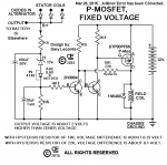
Fundamentally, some alternators have the regulator between the diode pack and the field coil. The other end of the field coil is ground.
Others have the regulator between the field coil and ground. The other end of the field coil goes to the diode pack.
1605069614856.png
The second way used to be easiest when NPN were the cheapest and best power transistors.
Where it says 'check relay' in pic, that is your warning light normally.
 

TernVI

Well-known member
Joined
8 Jul 2020
Messages
5,070
Visit site
Here's one where the neg end of the field is ground:
1605070442621.png
That's perhaps not the most mainstream implementation, but it shows that with modern choice of transistors, you can go back to grounding one end of the field which I think was normal back in the day of electromagnetic regs and even dynamo 'cutout boxes'.
People have posted better circuits which illustrate one field coil brush grounded, my internet is v slow here and I can't search effectively, sorry!.
 

DHV90

Member
Joined
23 Aug 2013
Messages
325
Visit site
thanks for that Ill read through those diagrams today and try and make sense of it. I believe my setup is what is shown in the attached image. WL terminal definitely has full battery voltage, with almost nothing at F.
I need to go back with the multimeter and do more tests, if you have any ideas for things to check it would be massively appreciated. The following things are things im thinking of checking at the moment -

Check resistance between Alternator Field terminal and both positive and negative terminals, to work out which way it is wired and to check that the brushes and slip rings are in good order (looking for open circuit to one terminal, probably positive, and lowish resistance to the other?)

look for continuity between battery positive and the hi/med/low terminal ( think it is currently on high )

To check if the regulator is between field and ground, am I right that there should be voltage at the WL terminal should have a closed circuit to battery positive? basically be an extended way of showing the resistance of the field coils?

Any checks I can do on the armature terminal?

Should there be continuity between WL and F on the regulator itself?

Thanks in advance, sorry none of this is obvious to me but its gradually getting clearer bit by bit!
 

Attachments

  • cav ac5 wiring.JPG
    cav ac5 wiring.JPG
    25 KB · Views: 13

TernVI

Well-known member
Joined
8 Jul 2020
Messages
5,070
Visit site
thanks for that Ill read through those diagrams today and try and make sense of it. I believe my setup is what is shown in the attached image. WL terminal definitely has full battery voltage, with almost nothing at F.
I need to go back with the multimeter and do more tests, if you have any ideas for things to check it would be massively appreciated. The following things are things im thinking of checking at the moment -

Check resistance between Alternator Field terminal and both positive and negative terminals, to work out which way it is wired and to check that the brushes and slip rings are in good order (looking for open circuit to one terminal, probably positive, and lowish resistance to the other?)

look for continuity between battery positive and the hi/med/low terminal ( think it is currently on high )

To check if the regulator is between field and ground, am I right that there should be voltage at the WL terminal should have a closed circuit to battery positive? basically be an extended way of showing the resistance of the field coils?

Any checks I can do on the armature terminal?

Should there be continuity between WL and F on the regulator itself?

Thanks in advance, sorry none of this is obvious to me but its gradually getting clearer bit by bit!
With the engine not running, the WL terminal should be low voltage, the light should be on.

First thing to check is the brushes.
Then check the bulb/holder/wiring, you've really already done this by seeing battery volts at the WL terminal.

From what I can see on the web, the field coil is connected to the diode pack and is energised by pulling current out of the F terminal on the alternator. So a low voltage here suggests the alternator is the problem not the regulator.
 
Top