Yikes! Any one know what to do here? Fibreglass structural problem under mast

yourmomm

Well-Known Member
Joined
6 Jun 2006
Messages
179
Visit site
Ok I've got this 50y/o boat at a steal, but it's in a pretty bad way, and it's my first fiberglass boat, so I'm not experienced with the material.

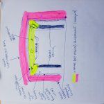
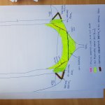
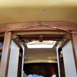
It's got a deck stepped mast, which looks like its had a fold at some point, as it's been heavily reinforced from underneath, with beams and steel angles, bolted directly into the port and starboard ply bulkheads, which make up the forward lockers (right hand photo).

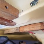
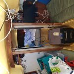
The problem is, these ply bulkheads do not meet the floor themselves, (they terminate at a thinnish fibreglass liner layer, approximately 12inches tall from the floor), and the forces from this reinforcement have obviously now been transferred straight down the bulkhead, (middle photo) and look like they've deformed the bottom fibreglass liner into which the bulkheads mount (left hand photo, with straight edge held in comparison, to demonstrate deformation). This deformation is on both port and starboard sides.

Any ideas to sort this, other than entirely stripping out the cabin, to get to and reinforce the fibreglass underneath the ply bulkheads...? (Or more likely just ripping the whole liner out and rebuilding the whole structure of the cabin, using wood instead....)

Thanks for your knowledgable advice, as ever...
 

Attachments

  • 20181019_130228.jpg
    20181019_130228.jpg
    271.8 KB · Views: 107
  • 20181019_130409.jpg
    20181019_130409.jpg
    393 KB · Views: 110
  • 20181019_130421.jpg
    20181019_130421.jpg
    301.3 KB · Views: 102
Last edited:
I wouldn’t have thought the bulkheads were designed to take the compression from the mast. My front bulkhead sits on a fibreglass beam like yours. The deck stepped mast sits on top of a compression post. You don’t say what make the boat is. Have you looked for an owners association that might have details of the construction.
 
It looks to me as if the mast load is supposed to be supported by the bulkhead (forward of the mast step) and the ring beam (aft of the mast step). This pic of another Storfrida 25 shows the structure quite well.

9e5199db12b3f430c5f4f2ddec1f8e01.jpg


It's maybe not the most robust solution, as you've found. If you're faced with finding a way of reinforcing the existing structure, maybe the answer is to try to strengthen the vertical sections which the longitudinal bulkheads bear on?
 
Whoa great find Babayaga, what search term found this? (Google only seems to find English websites for me). I have no idea what the text says but there seems to be a back and forth between two different ideas to try: the first, to try to place a spreader/support directly under the vertical beams, inside the fiberglass liner (I don't see how to do this, without stripping out much of the liner, to get access); the other seems to confirm pvb's idea to sister/strengthen the vertical supports. It looks like this may be possible without having to get too destructive, (although it would severely restrict the passageway, and would make my plan of putting a woodburner there, nigh on impossible....but needs must, when the devil drives).

Any other suggestions?
 
what search term found this?

the other seems to confirm pvb's idea to sister/strengthen the vertical supports. It looks like this may be possible without having to get too destructive,

Any other suggestions?

As mentioned above the boat's name is Storfidra, there is also a smaller sister, Havsfidra, which shares the same lack of central mast support. Some further search terms could be: mastfot (no need to translate), mastbalk (mast beam), maststötta (mast support), skott (bulkhead), förstärkning (reinforcement).
I think the last three posts by Misil-1 in the linked thread demonstrates a solution that might be successful.
 
Yes. I was after how babayaga's searched to reveal his link (in swedish)...Googling for me only brings up English language hits...

I've been having a closer look and my storfidra is built slightly differently to those photo'ed in his link, and pvb's post, above...there are already additional reinforcing vertical beams on mine, flush with and directly under the ring beam, which must have been added at the same time as the mast step was reinforced...they're done so well, I'd always assumed that they were original. But they too only go as far as the fibreglass liner, not all the way to the keel, so they've just added to the problem.

Fixing this problem by sistering additional support to my original beams, to align with the bulkhead support on the cabin floor, (in which I'd have to build a new ply bulkhead, connecting directly to the keel), is going to look ugly as hell, but is the only idea I've got at the mo....
 
I like your boat - hope you have some good sailing with her! You aren't alone in finding that the mast support structure isn't quite up to the job. A previous boat of mine had a similar problem. I ended up rebuilding the bulkhead with a central mast support stanchion and offsetting the door into the foc'sl. In your boat it looks like the settee fronts are structurally bonded into the hull and you are getting local deformation where the mast support stanchions bear on them. You might get away with a pair of plywood load spreaders bolted to the settee fronts and stainless tie bars from the stanchions to the plywood. It would be nice to hide it all behind the settee fronts, but that might turn out as disruptive as what I did! The ply could be painted up to match the GRP and wouldn't look too out of place, maybe.
 
Yeah thanks neil_s....funnily enough, I was considering supporting the mastfoot from directly underneath it, (in effect, making it keel-stepped) and hacking out those lockers, but i might as well plan for a whole new refit, if I did that.

I actually really like your idea of load spreaders bolted to those settee fronts, with tie-bars to the support beams already in place, although I think I'd also find a way for the load spreaders to connect directly to the keel, (via a new ply bulkhead), to be on the safe side. Cosmetically that wouldn't be as much if a problem as you may think as I'd planned to cover the whole lot of that ugly as yellow grp in mahogany overlay, anyway. Plenty to think about there...thanks for that idea.
 
Hi Jan, thanks for your PM. I couldn't work out how to send an image, so I'm replying here. The attached second image breaks down my third photo, in the lead post of this thread.

As can be seen, it would seem that the mahogany reinforcement to the underside of the mastfoot has spread the load force away from the original mastfoot support beam, both forward (onto the locker ply bulkheads) and aft (onto the newer, sistered mahogany beams and columns). Unfortunately, neither the ply locker bulkheads, nor the newer sistered mahogany columns extend to the keel, (instead are "supported" by totally inadequate 3-4mm polyester liner), so, as you say, it's just moved the problem of lack of appropriate mastfoot support from the top of the cabin, to the bottom!

I like your ideas to fix it. Before the bowsprit issues, I had already constructed and started to fit a new bulkhead in the keel, which sits under the cabin sole, as suggested by misil-1 in the swedish thread. My plan was then to loosen the shrouds, then jack up the original polyester mastfoot support beam/new mahogany reinforcement area, to relieve pressure on the whole support structure, and then temporarily fit a central compression post to keep the pressure off, connecting the original polyester mastfoot support beam, directly to the top of the newly constructed keel bulkhead. This would at least allow me to sail!

How to repair more permanently is still an issue. I dont think misil-1's idea will work on my boat, as he is sistering the original support columns, but on my boat, the newer reinforcement already placed fore and aft of the mastfoot has transferred much of the force away from the original mastfoot support beam, (and therefore, the columns underneath them). So the whole length of the buckling, deformed liner now needs supporting, not just under the original mastfoot support beam. Your idea of simply laminating a new marine ply panel to the inside of the liner was something I had considered, but its implementation is complicated by a lack of access (both from the settee top, and from the fact that the cabin end bulkhead, athwartships from the lockers, bisects the liner which needs support). This problem is not insurmountable, but I've got a lot of cutting up of the original liner to do, to gain access, and, as you say, since this liner seems to perform a structural function, all cutting must be carefully repaired again, afterwards. The situation is further complicated by the fact that the liner which has compressed was never vertical, so any ply panel somehow glued to the inside of it, would need additional athwartship bracing to the keel, both to the port and starboard.

I thought, overall, a better plan may be to try to get better access by removing the deformed liner entirely (curting it out, along its length), and use this access to support the vertical columns, and locker ply bulkheads, directly underneath, with a new, vertical, laminated 18mm ply panel. Also, to then support this new vertical laminated ply panel athwartships, with additional bracing, both inside the liner (under the settee tops) and outside, by constructing a new semicircular bulkhead, spanning the centre of the boat (Misil 1 has sort of done similar, by placing a length of mahogany above the cabin sole, above his new keel bulkhead: in his case, he was simply building up from the keel, to reach his new sistered columns, but his idea would also provide bracing support for inwardly acting forces on the original liner; in effect, I am proposing to do similar but to provide a much greater area for support, by the creation of a "step-through" bulkhead, similar to those seen in submarines). Tie rods could connect the vertical ply panel to the original columns and locker ply. Something like my first attached picture.

Although strong, this repair sure does seem complicated, though, so if I could get away with a more simple fix, (like laminating a panel to the inside of the deformed liner) I would happily do so! I think i will seek a marine surveyor's advice, as I have to get one done for my insurance company, in an event, but I appreciate your thoughts, and any more you may have.
 

Attachments

  • 20190107_102208.jpg
    20190107_102208.jpg
    281.6 KB · Views: 10
  • 20190107_133750.jpg
    20190107_133750.jpg
    266 KB · Views: 10
Maybe I have got it all wrong but it seems to me that it is the liner as you call it which makes up the sides of the bunk support that are failing (buckling). The structure down to that point is OK with all the additional reinforcement.
I would look the inside of those panels each side. Perhaps a cut out under the mattress often already cut out. While it will be fiddly you could reinforce the panel on the inside with lots of glass perhaps plywood glued on which goes right down to the hull. The advantage being that any (messy) reinforcement will not be seen.
I find the arched mast support very desirable but more complex compared to under mast support. It makes that entrance to the forward cabin nicer. So I would be reluctant to go to a keel stepped middle support. (as most boats have)
The load path for the mast pressure is from the bottom of the mast to the hull and thence to the chain plates so that path needs to be strong. good luck ol'will
 
Bolt a stainless plate to the berth sides? Would straighten out the crease and better spread the load into the liner. However, is the liner capable of transferring the load to the hull? I have my doubts... Maybe a ring of steel might be required? I think I would consider that but then look to Will's suggestion. Depends on whether you want a simple but visible fix or a complex but ultimately unintrusive one.
 
I have looked more closely at your alternative plans and also the Swedish tread.
The plan to cut out the bulged fronts is far form stupid, but you have to careful were cut (or keep your dinghy ready) and there are some other issues. I have stolen a picture from Misil-1 and added some lines. The arrow points to the bulge, as you can see. The panels marked with red is where the liner meets the hull. The panel is likely glued to the hull and transfer the load to the hull. You can check if I'm correct. In other words: do not cut below the almost vertical panel!
Storfidra.jpg

Before you proceed with the work; double check, if not already done, if the bulge really is a defect. This may sound like an odd suggestion, but I came across a very similarly looking bulge in my own boat, not a Storfidra and inside the bench front. It turned out to be the shape of a glassed in steel reinforcement plate. Clearly, it would be strange that it is not pointed to in the Swedish tread, if it's so.

Most ways to repair this will involve more or less grinding or sanding. This will produce dust. Remove all fabrics, cushions, mattresses and small items. Bring them ashore or pack in closed bags. If you think you will get away by just cover it with a sheet of plastic, you are wrong. You will be amazed how this dust travels and how hard it is to get rid of it.

There are some dustless options, like bolting steel plates on both sides or steel outside, plywood inside. In its simplest form, it will still be the single laminate that carry most of the load, the plates only prevent the laminate from bulging.

A similar, more demanding option is to glue plywood on the inside. For successful gluing you need to clean and sand the inside. You probably can reach it with a sander with one arm through the opening in the seat further aft. With a proper sander you probably don't need to see what you are doing while you do it. Then make a cardboard template, transfer it to plywood, round the edges, glass in the plywood, spread generous with glue (thickened epoxy), put it in place and screw it tight from the front side. After it has cured you may remove the screws and do a cosmetic repair of the bulge. The plywood should, if possible, go up in the little raised edge of the bench. It should follow the hull well, not cut in strait lines with angles.
If you can manage, try to laminate the angle between the plywood and the hull. This is tricky, but you can lay up the laminate on a stripe of plastic (PE) on a plate outside the bench, and transfer it to its place, riding on a stick, squeeze it onto the plywood and hull and let it cure with the plastic.

The alternativ approach, to open the bulged sides makes several things a lot easier. Now you can grind or sand the hull easily, and you end up with all new laminate. It opens the possibility to make a vertical wall that carries the load better, but you cannot just transfer the load to the hull, to a relatively short narrow line, you need to spread it. The bench front was meant to do this job. The main problem seems to be that it was not stiff and strong enough at the top to take load before it had the chance to spread it.
There is another thing that complicates the solution to just remove the fronts; The bulge is quite far up and you will need some undamaged laminate to tie to. The laminate behind the bulge will likely be crushed and not suitable. You can end up in removing the woodwork above just to get a good bond.

It is easier to get a strong new front than a stiff one. You will need the stiffness. This is best achieved by making some kind of sandwich. Easiest available material is plywood. For long time durability you need to protect it against water, you need to glass it in. This can be done before you put in place. Instead of fasten it with glue and screws, you put in place and laminate the new front wall laminate on to it and the beveled edges of the hole.

The devil is in the details!
 
Last edited:
There seems to be a lot of focus on transferring the load of the mast to the hull (bottom). Wouldn’t it be better to think more of the connection to the chain plates where the bulk of the load comes from?
 
Top