Steve_N
Well-Known Member
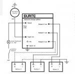
I picked-up on eBay a Driftgate X-split MOSFET charge splitter which, although a blast from the past, seems to be still marketed under the Durite banner.
I'm not entirely sure what the 'sense' connection is for? - wiring diagram attached - so I'd welcome some help please. Thanks.
I'm not entirely sure what the 'sense' connection is for? - wiring diagram attached - so I'd welcome some help please. Thanks.