Wiring woes

"PaulRainbow, said
If you connect it to a + terminal, as you suggest, it will never come on and there will still be no initial excitation.

It should be wired from the ignition switch to the positive output of the field diodes/ input to the regulator.


Is that D- or D+ ? The Prestolite image of the rear of the alternator looks very much like D-, as does the OPs pic, but the schematic states it' D+

In 2 of the 3 photos it definitely looks like D-. There are two schematics in both the owners manual and the 'shop manual. One shows the main alternator output terminals as B+ and B-, the other as B+ and D-


Where to you get the idea that the wire is negative ? The Prestolite picture and diagram both show this wire is in the correct position.

OK lets just call it " the black wire on the capacitor"


It's a sketch of the Prestolite image i posted, but it has the negative wires on the D+ terminal.

I assumed PP's sketch was an accurate representation of the alternator actually fitted. Not very helpful if it is not. Very disappointing if it is not.


It would be very helpful if the OP revealed the answers to the two questions in post #7

Perhaps he does not understand the question


Why would you connect the warning lamp to a positive terminal ?

It should be connected to the positive output of the field diode / the field input to the regulator, When the ignition is switched on there is no output from the field diodes and the current flowing through the warning light will provide the initial excitation current . When the alternator starts generating the output volts from the field diodes will rise and the light will dim eventually extinguishing when the volts equal the battery volts. The field current will then be supplied by the field diodes.
 
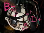
I think two Black negative wires and the brown lamp wire must be right. I'll let you know how it turns out

It is NOT right

The brown wire is the warning light. If it is connected to the battery negative connection it will come on when the key switch is switched on and stay on. The alternator will not get its initial excitation and is unlikely to generate .

If it does not go to the + terminal there must be another connection for it which you have not shown in your sketch or photos

How about connecting it to the D+ terminal, where it belongs.

Possibly connect the two black cables to the B- terminals ?

Every terminal is clearly identified in the Prestolite link i posted.

Forget what the engine manuals say, it's hardly likely the VP fitted Prestolie alternators to those old engines.
 
I cannot tell if the D terminal is plus or minus. It could be either. The labelling is not good. How can I check to be sure?
 
Yes, all the cables have been off when we took the alternator off. Yes I put the cables back and I do not know if it is right, this is my problem.
 
Last edited:
The wiring diagram drawing I did is how I have reconnected it
I have not switched anything on yet, nor will I until I can get this sorted.
 
The wiring diagram drawing I did is how I have reconnected it
I have not switched anything on yet, nor will I until I can get this sorted.

OK, this makes it easier.

All wires are correct, except, the two black wires are wrong, they should go the the terminal marked B-, that's the stud next to the W terminal.
 
Last edited:
It should be wired from the ignition switch to the positive output of the field diodes/ input to the regulator.


That's the D+ terminal then, just aboce the B+ terminal.

In 2 of the 3 photos it definitely looks like D-. There are two schematics in both the owners manual and the 'shop manual. One shows the main alternator output terminals as B+ and B-, the other as B+ and D-


It's not the best + i've seen, but the schematic clearly identifies it as D+

OK lets just call it " the black wire on the capacitor"


Again, clearly shown as in the correct place, on the Prestolite picture and schematic.

Perhaps he does not understand the question


"Has it been off and you put it there ? What size is the nut on this terminal ? "

Not hard questions


Why would you connect the warning lamp to a positive terminal ?

It should be connected to the positive output of the field diode / the field input to the regulator, When the ignition is switched on there is no output from the field diodes and the current flowing through the warning light will provide the initial excitation current . When the alternator starts generating the output volts from the field diodes will rise and the light will dim eventually extinguishing when the volts equal the battery volts. The field current will then be supplied by the field diodes.

Oddly enough, i'm aware of how the charge warning lamp functions. You correctly stated earlier that this should be connected to the D+ terminal (or 61).

I think what's causing some confusion here it the slightly poor marking of the D+ terminal. It also isn't helping that some people have not looked at the Prestolite link i posted.
 
Yes I looked at the prestolite link. Very helpful, if it's correct!!! The B- is not marked as such on my alternator, and yes, the confusion is over the poorly marked terminals. If they were clearly marked I might not be asking here.

I will endeavor to measure the stud sizes next time I'm aboard. I'm not sure when that'll be given how things are at the mo.
 
So to summarise
B- neg/ground/earth. Thick black & a thin black wires
W rev counter. Thin Grey
B+ pos/ Batt via solonoid thick & a thin red
D+ dash light. brown
+. Capacitor Black
 
I think what's causing some confusion here it the slightly poor marking of the D+ terminal. It also isn't helping that some people have not looked at the Prestolite link i posted.

I posted the Presolite pic of the alternator and the schematic, which clearly states it's D+, but we still have the multitude of blatantly wrong replies above :mad:

"slightly" poor is an understatement

Even the picture of the back end on the website is just as unclear

Several of the relevant terminals cannot be identified at all

The schematic you keep referring to does not help either:

Prestolite alternator schematic.jpg
 
Last edited:
"slightly" poor is an understatement

Even the picture of the back end on the website is just as unclear

Several of the relevant terminals cannot be identified at all

The schematic you keep referring to does not help either:

View attachment 87103

Wouldn't say it's the best marking i've seen, by a long shot, but if you zoom in on the Prestolite image it's clear. The last pic the OP posted looks clear too.

Not sure why the schematic doesn't help, looks crystal clear to me

http://www.prestolite.com/productinfo/alternators/66021151M/66021151M_dim_r.jpg
 
Top