Talulah
Well-Known Member
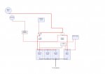
My tuppence worth. Newer versions of 1/2/B/Off now have 4 terminals. Legacy switches have 3 terminals. These newer switches also act as the domestic supply on/off switch. In the first position the house supply is switched on. The next position turns on the engine battery. So now domestic and engine are live. 3rd position is both paralleled together
Last edited:
") )
)