Winter wiring project

Tinto

Well-Known Member
Joined
25 May 2019
Messages
220
Visit site
Hi All
I will be re wiring the charging side of my boat this winter as it’s a bit of a mess at the moment.

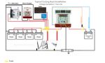
I have included a schematic I found on line and added to.

i have two alternators on the engine, 50A and 70A, and those have blocking diodes which need replacing.

am I correct in saying all other charge sources would also require blocking diodes? If so where would I buy them and what spec?

Is there a better method of protecting devices than blocking diodes as these soak up power and their heat sinks take up space
 

Attachments

  • 5DC5B5D9-0B04-4E65-B47E-CDC05B325AD7.png
    5DC5B5D9-0B04-4E65-B47E-CDC05B325AD7.png
    105.2 KB · Views: 51
Fit a positive busbar and connect all of those positive charging and load cables to it, each one fused (although alternators are not commonly fused). Fit cable between the busbar and the batteries combined current of all of the loads/charging sources and fuse that at the battery.

I don't see anything in your schematic that would need a blocking diode. What diodes do you currently have and where are they fitted ?
 
At the moment each alternator has a diode in the circuit. These allow both alternators to charge the house and start batteries without the output from alternator 1 feeding into alternator 2.

So my question is. Don’t I need to protect the aquagen, wind turbine and MPPT controller from the 70A output of the larger alternator? This schematic shows all these commoned on the one bus bar.

No.

What alternators do you have fitted ?

Where are the blocking diodes fitted ?

What diodes are they ?
 
At the moment each alternator has a diode in the circuit. These allow both alternators to charge the house and start batteries without the output from alternator 1 feeding into alternator 2.

So my question is. Don’t I need to protect the aquagen, wind turbine and MPPT controller from the 70A output of the larger alternator? This schematic shows all these commoned on the one bus bar.

It would be unusual and normally totally unnecessary to fit diodes for this purpose.

Are you sure they aren't split charge diodes, designed so that each alternator can charge the engine and domestic batteries, whilst keeping them isolated from one another ?

Split charge diodes: split charge diode - Google Search
 
yes, that’s what they do

Don't replace them. Looks like you are fitting a Sterling battery to battery charger, if so, just connect both alternators to the domestic bank. You can connect the charging cables to the main battery terminal of the starter motor solenoid if it's more convenient than connecting to the batteries/busbar.
 
Don't replace them. Looks like you are fitting a Sterling battery to battery charger, if so, just connect both alternators to the domestic bank. You can connect the charging cables to the main battery terminal of the starter motor solenoid if it's more convenient than connecting to the batteries/busbar.
Hi Paul
As I understood it, the Sterling battery to battery charger does the job of the diodes but in a more modern and efficient way, so I can then take those out of the circuit. Is that not correct?
 
Top