Vosper information

BCarmena

New Member
Joined
1 Apr 2021
Messages
10
Visit site
Hello all,
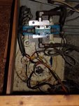
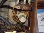
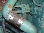
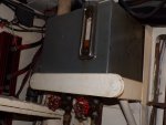
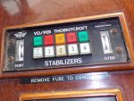
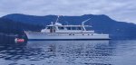
We purchased a 1969 Stephens Brothers aluminum last year. I am in the process of completing maintenance that has been neglected for many years. One item on the list is our Vosper stabilizer system. The system is non-functional but all of the equipment seems to be intact. The main problem is that someone has done a very disastrous job of attempting wiring repairs on the system. I am trying to rewire everything from the controls to the solenoids/position sensors. Unfortunately I have no documentation for the system. The boat came with most manuals but unfortunately not this one. I have opened the control modules just in case someone left a wiring diagram tucked inside as was common in those days but to no avail. Does anyone have and diagrams or manuals for this system or know where they can be had? The boat is coming out of the water this coming Monday as well and one of the items on the list is to completely disassemble the units, inspect, service, and reinstall. I am not completely sure how the units come off. I have heard of hydraulic tools to push them off of a taper but in the pictures that Vas posted in his retrofit thread it does not appear that the Vosper units are held with a taper like the Niaid Fins. What types of tools would I be needing to remove these? I have been a marine technician for many years however I have never had to remove one of these. Any help would be very much appreciated. Thanks in advance!
 
This might help for the removal.

HELP! Vosper Stabilizer Fin Removal - Trawler Forum

any idea what your exact vosper model is?
I believe it is the Maxi fin unit from previous owners correspondence with the boatbuilder. Most of.the equipment looks like the unit pictured in the MiToS retrofit. I had seen that post on the trawler forum but the info on there is based on a Niaid fin which is a different shaft compared to the Vosper unit on MiToS.
 
I bought s/h a Vosper system, installed it in my boat but in the process scrapped the analogue box of tricks and running off a custom PLC (arduino style) board.
I do have the manuals / installation / wiring in paper format.
Post a couple of pics to establish we are talking about the same thing and then we see how we progress.
OK, so you did find my thread then :)
had a long day today, so will come back tomorrow

V.
Vas,
I did follow your thread. I have plans to do a similar upgrade to my system. Your setup was quite impressive. I will take some pictures this evening and post them up. Thanks!
 
good morning, realised that you've read my thread halfway typing halfasleep my message, when I re-read properly you post :)

Right, IMO and before taking anything apart it would be worth checking where you stand now:

A. pulleys/oilpump/oil in system/filter/cooler all fine - nothing leaking?
B. pulley permanent on engine I guess?
C. system on (ignore electrics) oil circulates/no leaks?

Now, as far as cabling goes we have on each side two solenoids, each operating the respective ram and the position sensor which is in the cover under the tin "lid" on the top of the shaft
Ignore the later (I guess that's where your problems are).
as seen in the video above that's your wiring!
now notice the bright coloured (on mine at least) buttons at the end of the solenoids. These are manual overrides.
So with system up and running (and obvs fixing pins if -available- removed!) press one of them and the ram will extend, press the other, the other ram will extend...
If that lot works and there's no water leaking in (doubt it!) I'd question the need to disassemble them tbh.

Disassembly means you undo the 20something (or is it 30something!) mm nut on the bottom of the fin and pull it down - shaft bolt is bronze btw. Mind thing is rather heavy so once it frees (don't know how easy that will be!) it will come crushing down to your feet, take care!
You have nothing to do now outside, just get inside for the rest.
Bearing in mind that the only thing that needs careful alignment/setup is the position sensor, I'd urge you to be v.careful there!
By taking the lot apart you will in reality accomplish two tasks:
replace the stuffing box material (I didn't! just removed the top ring - iirc there are three or four and replaced with new)
renew the bushes on the hammerhead side of the central shaft. These get a decent hammering as hydraulics are not progressive. Couldn't find imperial bushes and ended up getting the holes machined for suitable and available metric ones and fitted them.

Again, removing the position feedback sensor or however it's called needs care and good markings so that it fits right and the analogue control will get the fins back straight with minimal manual fine tuning later.

Now in terms of paperwork, I do have a folder with everything, but on a quick check here at my home office didn't find it. Pretty sure I've not scrapped it, 99% is still onboard, will come back on that.
but as I said, cabling is really silly simple (unless they've messed with the 3 (iirc) cables that go to the position sensor. The others are 24V going to each actuator from 4 massive analog relays (JTX-2P ) that live in the box.
Mind James (silverdee) who gave them to me did mention that these relays failed regularly so had a stock of them onboard (10-20euro ea I think)

I'd try and drive with 12 or 24V not sure what your installation is each solenoid and make sure it engages, then get back to the box and check continuity on cables.
If all that's fine and all four solenoids do get power from the box (check the relays!) then it's either in the box or the position sensors and things get more complicated.

pics of installation, wiring, solenoids as well as testing ABC above would help!

V.
 
Thanks so much for your reply! Unfortunately I cannot currently test the hydraulics as the hoses are in very poor condition and I do not trust them enough to pressurize them. I will be replacing them in the near future. Pumps are mounted directly to the PTO outputs on the back of each engine and are gear driven. The electronic control units seem to be clean and corrosion free however the control panel does not display correct fin position when powered up so I wager either the poor wiring is the culprit or a failure of the position sensor itself. The solenoids are easy enough. One has been replaced already and I have a new solenoid and valve body for the stb side ready to go on when I replace the hoses. Currently, only the stb valve body has the ability to be manually engaged. The fins are getting removed mainly for inspection. The main purpose of this visit to the yard is to check everything below the waterline. I will post up more pics of the wiring and control boxes when I get a moment.

Blaine
 

Attachments

  • Vosper port.JPG
    Vosper port.JPG
    689 KB · Views: 81
  • Vosper stb.JPG
    Vosper stb.JPG
    793.1 KB · Views: 76
  • Port pump.JPG
    Port pump.JPG
    400 KB · Views: 74
  • Reservoir.JPG
    Reservoir.JPG
    775.2 KB · Views: 75
  • Panel.JPG
    Panel.JPG
    974.1 KB · Views: 74
Blaine,

rather rusty down there :)
good idea to clean and get them all checked. Looks like the controllers are not in the e/r, wonder why they are in such a state!
Shall I guess that the one that the position sensor is not reporting right is the uncovered one with the replaced control valve assembly with the vickers?
BTW, my control box is rather different, wonder if yours is less analogue compared to mine...
Was on the boat this evening for a short time, forgot completely to search for the manual, will do tomorrow.
Position sensors are Penny and Giles, company still alive you may contact them and after checking the serial # or codes try to find alternatives.
Am I right in assuming the fins where more or less installed back then? If so, and if the fins have had some use, the position sensors must be shot! One of mine was badly "worn" in the area that it was working (OK circa 40degrees) so I just moved it around to another area I would get "clean" and smooth resistance signal from the potentiometer (it really is a simple potentiometer) and altered my s/w. You cannot do that, system works based on the right values, if they fail, system goes haywire I guess...

Mind running the engines would get oil around anyway PTO unless I'm way off has no on/off! OK if the solenoids are all open allowing oil to freeflow there wont be any pressure built up in there, so you are fine.
Although it sounds odd, I'd try replacing all the hoses with new ones and testing the operation of the system before dismantling, just to have an idea what works and what not (and to move the shaft about a bit in case it's slightly stuck...
We do like photos here, and looks like an interesting boat, post a couple of pics of the whole craft plz! how many feet, over 60?

cheers

V
 
Yes indeed it is rusty. Previous owners unfortunately let things go way too long. The position sensors don't seem too fancy. I could likely find a newer alternative with matching ranges that might be a bit more robust. Failing that, just get replacements from Penny and Giles. At my business we do custom fabrication and electronic fuel injection conversions so I am quite comfortable with that stuff. I would eventually like to get the system running on an Arduino with yaw, pitch, and roll data coming from my satellite compass via NMEA2000. I have not yet dug far enough into it to know whether the data has a high enough rate to be useful though. My next project coming out of the yard will likely be the stabilizers. I will get the lines done and go from there. In the worst case I should be able to figure out the solenoid wiring by manipulating the gyro box. Failing that I will just tackle the Arduino project sooner! :)

We love the boat. It was in rough condition but we are slowly pecking away at repairing and updating systems. The battery bank has been updated to a 24v LiFePo system with 1400ah worth of charge. I am also currently replacing the gensets with two 10KW DC generators as this is much more efficient for our setup. We have also installed 2400W of solar so can go for weeks without running a generator. The high voltage side is provided by two Victron Multiplus inverters providing 220v for appliances. The boat was previously used as a dive charter boat in Mexico so came equipped with a dive compressor, 1000 gallon per day watermaker, and a few other bonuses. LOA is 78 ft with a beam of 17 ft. She was lengthened in the 80's from her original 65 ft. The rear deck area is all tankage. She holds 3000 gallons of fuel so range is pretty good all considered. We will be doing a repower next winter with something considerably more efficient so range will only get better. All in all we have a long way to go but its slowly getting to a point where we will be comfortable travelling the world with her.

Sorry for rambling but I suppose everyone likes talking about their boats.

Blaine
 

Attachments

  • Tangaroa.jpg
    Tangaroa.jpg
    404.6 KB · Views: 92
sorry, thread dropped off the first page and forgot about it.
I found the manual (was at home on the wrong shelf), unfortunately work secretary with her nice autofeed scanner is off due to covid and I wont scan 50odd pages at home on a flatbed.
If there's something in particular you'd need let me know, I'll scan the el.diagram with wire colours (I think they are mentioned) maybe it will be useful

V.

PS. lovely boat not sure about the legthening though and how that affects even stabilisation
 
No worries at all. We are still pecking away at the yard. I got the stabilizers apart and removed no problem. The ram bearings were toast but everything else looks OK. I had the bases sandblasted while the were doing the hull so no more rust. The hoses were completely done so I will be replacing them all. The pumps seem fine. The only thing in the manual that would be really nice is the wiring diagrams. I have the rest of the system all figured out. I appreciate your help.

We really do love the boat. The extension was a bit odd at first but has really grown on us. Rudder placement is not ideal but that can be addressed in the future. We have had her in pretty decent following seas and she is not unmanageable.
 
good morning,

on a series of meetings today/tomorrow, will steal some time and post it before the w/e
What do you mean ram bearings? the small odd looking bearings that are two per shaft and where the end of the ram is joining the main shaft, right?
they get a v.decent hammering from the two rams!
only solution (and I'm starting to work on that now) is getting the hydraulic valves replaced with proportional instead of on-off. This way the almost 200bar of pressure will ramp up so rams will hit the bearings with much lower force at the start of the fin travel (wouldn't care that much on the stopping tbh)
obvs this means you rework all the electronics with a new controller alltogether - wont be able to use the existing valves.
Since I did some work for the first time with compressed air valves (similar concept) I'm trying to work out how to do it and then shop around for the bits needed (not that cheap probably close to 1k per side for valve hardware)
Then you may have to think about changing the pumps to swash plate ones and that's some extra as well, we'll see!

cheers

V.
 
Hi BCarmena -Lovely ship congrats. just my 2pence worth here and feel free to ignore me.
But before you spend money on those v old stabs have you thought about total new zero speed system? The modern stuff is amazing and will work many times better. IMHO the single biggest/best upgrade you could do is just that and i would prioritise it well above lots of other expensive new nav kit etc. I get the impression you are not scared of a big job and that you want to do some serious time onboard- getting stabilisation right is the difference between happy boat life or not. Even underway and fully working your current system will sometimes be overpowered in a chunky beam sea. I had that system as vas says for 15 years around the uk on previous boat and eventually upgraded that boat to sleipner and now on current boat changed original circa 2000 year koopnautic for sleipner sps66 a couple of years ago. lots of systems to look at -humphree electric- easy to fit. Sleipner (clearly i am a fan) ABT- lots of folk think they are bomb proof etc. on a boat that size you might want a lot of hydraulics anyway esp bow / stern thrusters -25hp continuous duty plus maybe anchor winch/ stern capstans - crane-passerelle. just sayin` anyway good luck your refit I`m sure the folk on here would love to see details as you progress. Where are you doing the work?
 
Vas,
I was indeed referring to the 4 spherical bearings (2 per stabilizer). The proportional valves could certainly be programmed to provide a considerably less harsh engagement. I wonder if you could alternatively use brushless DC motor powered pumps and use speed control to achieve the same effect. This would also allow some stabilization at anchor and would eliminate the need for the valves all together.

Silverdee,
Thanks! The stabilizer system is very low on the priorities and based on cost vs benefit of a new system will unlikely ever be replaced by us. I grew up on sailboats and my wife and I worked on sailboats for years together so roll does not concern us in the slightest. We have been cruising with the boat for over a year now with the stabs not functioning and have not really been uncomfortable ever. She has a fairly slow roll. Sure, a new system would be great but its just not in the budget. I mainly am repairing them because I can't stand non-functioning systems. Currently everything is electric on the boat. We have an ideal windlass with a 24v motor and the boat already has a Lewmar electric rear capstan/windlass (she came with a stern anchor). It has no bow or stern thrusters but actually maneuvers quite well without. Due to the age of the boat the styling is deep, narrow, and not very tall so windage in docking situations does not affect her much. We are doing all of the work at Steveston Harbour in Vancouver on Canadas west coast. I will try to post pictures as we go.

Blaine
 
Fair enough Blaine - beautiful boat enjoy. Vospers are still (i think) in Southampton if you want to email me james.maxey@expresssolicitors.co.uk ( don`t look on here that often) i could dig out some contact emails and maybe manuals etc as i was in touch with them on and off for refurb work/ parts/ spares on mine up until circa 2015.
 
oops, forgot again!
this is the el. diagram, was trying to find a loose page that James gave me with the stabs (not on the full Vosper folder I also got), cannot find it, only got a scan/photo of it. Save it, zoom in a lot, you'll get your way through it I recon.
2018-04-17-22.24[4web].jpg
 
Vas,
I was indeed referring to the 4 spherical bearings (2 per stabilizer). The proportional valves could certainly be programmed to provide a considerably less harsh engagement. I wonder if you could alternatively use brushless DC motor powered pumps and use speed control to achieve the same effect. This would also allow some stabilization at anchor and would eliminate the need for the valves all together.
owe you a reply on that.

You've probably noticed that I'm using a 3ph 5kW motor to run a 8lpm (I really don't remember now, got to check my docs again, started with 16lpm which was too big, now either 4 or 8) pump to run them at anchor. I also have a new pump running them with an el.clutch off port engine when under way. Of course tees and non-return valves before going to the control valves.
The reason for that was to be able to establish what rpm will produce enough flow/press needed for different conditions.
Started working on this again last week altering my s/w.
For starters fin shape/area is not good enough for STAR operation, need to lengthen them. I did the other way, chopped a few inches from the bottom to alter proportions, not enough, does work up to a point but needs to shift more water, so need to be longer. Next week boat will be on the hard and I'll try to address that.
Note you need a circa 5kw motor to pump enough oil at enough pressure. Can you do that with DC brushless? and what battery bank will drive that? BartW who's running el. stabs on a larger planning hull has a hell of battery bank to support operation without running his geny.
Need v.fast alterations of oil flow/pressure, not sure you can achieve that with the motors alone, I think you'll need a control valve mechanism. I've tried altering the Hz of the inverter running this 3ph motor, have to code RS485 signals to alter that in real time, not sure how fast it can be on a ms level.
Finally tried to test my s/w with PWM control (v.crude, like turn solenoid for 200ms, turn off for 50ms and loop) failed as my plain board cannot drive with enough current the solid state relays I'm using. Will upgrade that with a servomotor chip and see where I get. Gut feeling is will need to replace the control valve assembly on top of each stab. Relatively easy job except for matching threads and hoses, should be dead easy to program and will make bearings life much easier and less banging inside.
See how bored I'm during the summer and could go ahead (a grand worth of h/w last time I checked a few years back)

cheers

V.
 
Am a recently registered member, but followed this thread in the past. Wondering if the folks involved in this thread still around?

Am looking for a Vosper Mini Fin to replace one that was lost - also looking for any parts available associated with potentiometers, flex couplings and the like, mounted an the stabilzer shaft

All goes to repair/maintain a system (actually 2 systems) aboard an 80' 1947 Trumpy .

Cheers - Jack Boyt
 

Attachments

  • Stabilizer specs.jpg
    Stabilizer specs.jpg
    452.2 KB · Views: 26
hi and welcome to the forum,

afaik, we are all still around - busy with other things mostly...
I've bought my system from @silverdee old boat. Never contacted the co which silverdee had done in the past. It was mentioned that my fins were the last built by the company, no idea if they still have the moulds and/or are willing to built a set or two for you.

cheers

V.
 
good morning, realised that you've read my thread halfway typing halfasleep my message, when I re-read properly you post :)

Right, IMO and before taking anything apart it would be worth checking where you stand now:

A. pulleys/oilpump/oil in system/filter/cooler all fine - nothing leaking?
B. pulley permanent on engine I guess?
C. system on (ignore electrics) oil circulates/no leaks?

Now, as far as cabling goes we have on each side two solenoids, each operating the respective ram and the position sensor which is in the cover under the tin "lid" on the top of the shaft
Ignore the later (I guess that's where your problems are).
as seen in the video above that's your wiring!
now notice the bright coloured (on mine at least) buttons at the end of the solenoids. These are manual overrides.
So with system up and running (and obvs fixing pins if -available- removed!) press one of them and the ram will extend, press the other, the other ram will extend...
If that lot works and there's no water leaking in (doubt it!) I'd question the need to disassemble them tbh.

Disassembly means you undo the 20something (or is it 30something!) mm nut on the bottom of the fin and pull it down - shaft bolt is bronze btw. Mind thing is rather heavy so once it frees (don't know how easy that will be!) it will come crushing down to your feet, take care!
You have nothing to do now outside, just get inside for the rest.
Bearing in mind that the only thing that needs careful alignment/setup is the position sensor, I'd urge you to be v.careful there!
By taking the lot apart you will in reality accomplish two tasks:
replace the stuffing box material (I didn't! just removed the top ring - iirc there are three or four and replaced with new)
renew the bushes on the hammerhead side of the central shaft. These get a decent hammering as hydraulics are not progressive. Couldn't find imperial bushes and ended up getting the holes machined for suitable and available metric ones and fitted them.

Again, removing the position feedback sensor or however it's called needs care and good markings so that it fits right and the analogue control will get the fins back straight with minimal manual fine tuning later.

Now in terms of paperwork, I do have a folder with everything, but on a quick check here at my home office didn't find it. Pretty sure I've not scrapped it, 99% is still onboard, will come back on that.
but as I said, cabling is really silly simple (unless they've messed with the 3 (iirc) cables that go to the position sensor. The others are 24V going to each actuator from 4 massive analog relays (JTX-2P ) that live in the box.
Mind James (silverdee) who gave them to me did mention that these relays failed regularly so had a stock of them onboard (10-20euro ea I think)

I'd try and drive with 12 or 24V not sure what your installation is each solenoid and make sure it engages, then get back to the box and check continuity on cables.
If all that's fine and all four solenoids do get power from the box (check the relays!) then it's either in the box or the position sensors and things get more complicated.

pics of installation, wiring, solenoids as well as testing ABC above would help!

V.
In rereading this post, was wondering what preferences exist for pulley based hydraulic pump vs direct drive from PTO?

thx
 
Top