Volvo Penta Alarm Module - Simpler fix

If it is of any help, I can provide professional PCBs, either built or bare if I can get all the info together to do the design. Bare boards work out at a couple of Pounds each.

Size?
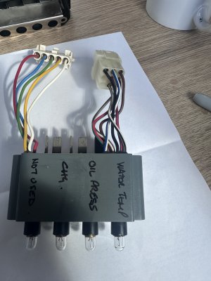
What connectors are needed?
 
This is interesting, what info would you need please?

As much as possible about the original. Photo of it, the size of the board and style of connectors would help to make it a five minute drop in replacement. If I have to make best guesses, the board may not be so easy to incorporate. The Veroboard version would help too.

I could make bare boards available for discrete components, for SMD or maybe fully populated once I come out of hospital (heart surgery) and sufficiently recovered.

All suggestions and information are welcome.
 
In the past I have seen this circuit used for a very much simplified unit using just diodes:

1774464187839.png

The limitations are the audible alarm only works on pressure and temp, not alternator. The buzzer sounds when engine stopped until ignition turned off (because of the deleted transistor).

What does the team think? I assume that LEDs could be used with appropriate resistors.
 
In the past I have seen this circuit used for a very much simplified unit using just diodes:

View attachment 208289

The limitations are the audible alarm only works on pressure and temp, not alternator. The buzzer sounds when engine stopped until ignition turned off (because of the deleted transistor).

What does the team think? I assume that LEDs could be used with appropriate resistors.

Simple is good, but I would prefer function over simplicity. I have in my head some over engineering...

Port Temperature high? Buzzer sounds .--. - starboard oil and buzzer sounds ... --- etc. Simple enough with a Nano etc and cheap to implement. I like such gadgetry but I would imagine that I am in the minority!
 
If I can get the old Volvo unit to work, I’ll be chuffed

From what I read further up, it may just want a new Zener diode. If you have it loose, you could send it over to me and I will see what I can do for you before I go into hospital.

I have a Targa 27 and I didn't get an audio alarm from my recent overheat, so I will have a little look to see what I have in there next time.
 
Last edited:
From what I read further up, it may just want a pair of new Zener diodes. If you have it loose, you could send it over to me and I will see what I can do for you before I go into hospital.

I have a Targa 27 and I didn't get an audio alarm from my recent overheat, so I will have a little look to see what I have in there next time.
OK, unit is out. I have the diodes, as per the pic.
I’m assuming it’s just a case of cutting each of the wires & soldering in a diode for each:
Brown = alternator (charge warning)
Blue & white = oil pressure
Brown & white = water temp
In my case, the green & red (exhaust temp?) is not used.
Which way round for the diode(s)?
 

Attachments

  • IMG_3927.jpeg
    IMG_3927.jpeg
    1.5 MB · Views: 10
  • IMG_3928.jpeg
    IMG_3928.jpeg
    59.2 KB · Views: 9
OK, unit is out. I have the diodes, as per the pic.
I’m assuming it’s just a case of cutting each of the wires & soldering in a diode for each:
Brown = alternator (charge warning)
Blue & white = oil pressure
Brown & white = water temp
In my case, the green & red (exhaust temp?) is not used.
Which way round for the diode(s)?

You have purchased the standard rectifier diodes, but according to information above, it is the Zener Z1 which needs replacing. As for polarity, one end of a diode is marked with a band. Just replace like for like.
I wouldn't be swapping out the rectifier diodes without testing them first though, they are pretty hardy and unless obviously burnt are unlikely to be faulty.

Can I see the other side of that board please?
 
Last edited:
The “board” is actually a sealed block of plastic, with the connections & wires protruding from the back, there is no sign of the board itself, nor of the diodes. I assume the diodes are inside the sealed block.
I sourced the diodes after referring to the diagram supplied by one of the other contributors above & they are as he listed on the diagram IN4001S.
 

Attachments

  • IMG_3930.jpeg
    IMG_3930.jpeg
    1.4 MB · Views: 5
  • IMG_3929.jpeg
    IMG_3929.jpeg
    1.9 MB · Views: 6
The “board” is actually a sealed block of plastic, with the connections & wires protruding from the back, there is no sign of the board itself, nor of the diodes. I assume the diodes are inside the sealed block.

That's a shame, it is unlikely that you will be able to get into that, so we will likely have to produce a board to go with it and bypass it.

I sourced the diodes after referring to the diagram supplied by one of the other contributors above & they are as he listed on the diagram IN4001S.

Yes, those are the correct rectifier diodes, but the post said that the Zener diode was going to be dead. Marked Z1 on the diagram. As you can't get into the board, you can't replace them.

How do you feel about posting me that block to inspect?
 
Last edited:
That's a shame, it is unlikely that you will be able to get into that, so we will likely have to produce a board to go with it and bypass it.


Yes, those are the correct rectifier diodes, but the post said that the two Zener diodes were going to be dead. Marked Z1 on the diagram. As you can't get into the board, you can't replace them.

How do you feel about posting me that block to inspect?
No way to get into that block without breaking it open.
I understood that the fix, which appears to have been successful, is to put the diodes in the wiring to the block, as per previous posts here.
I’m going to do some more testing on the unit before making any repair attempts.
 
No way to get into that block without breaking it open.
I understood that the fix, which appears to have been successful, is to put the diodes in the wiring to the block, as per previous posts here.
I’m going to do some more testing on the unit before making any repair attempts.

I will look at the thread again then, as I may have misunderstood. Apologies if so.
 
"Simply connect diodes +VE line towards the Blue / White (oil pressure) and Brown / White (temperature), with both neg wires to the Black connection. This should restore the alarm buzzer function by grounding (to -VE) out the test circuit if an individual alarm illuminates"

Right, it appears that the banded ends will connect to Blue/white and Brown/White. the other ends of the diodes will be commoned and connected to the black wire according to that. It is a bit ambiguous though as you wouldn't normally refer to diodes as having a +Ve line or "neg wires". @superheat6k

Diodes D9, D10 & D11 can be externally connected in opposite polarity to the coloured wires to repair a module with a blown Zener (Alarm buzzer test works, but individual alarms do not sound buzzer)
 
Last edited:
Top