wolves88
New Member
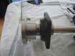
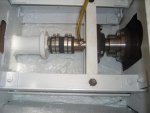
Hi all, new member here, I am in the process of fitting a reconed 1.8 BMCwith a hurth ZF 10m box and I have a 1 ¼” shaft and coupling into my semi restored Colvic 20, my problem is because the angle of the shaft where it meets the gear box flange is not flush” I have dropped the engine as low as poss to meet it” but to get it in line would need to raise the front of the engine some 3+ inches higher creating what looks like too much slope for the engine to run at i.e. oil in sump. So being a car man I managed to find a small 16” 4x4 pro haft with a U J and a flange each end that match my box and shaft flanges, my worry is how do I null the thrust will a heavy duty pillar bearing just before the stern tube do or is this idea a no no? I am way over budget and don’t want to go down the aqua or python drives route, any advice please thanks Barry