Two 12v supplies on one Seatalk network

[2574]

...
Joined
29 Nov 2002
Messages
6,022
Visit site
I have a Seatalk 1 network (ST60) bridged via a Seatalk:SeatalkNG converter to a Seatalk NG network. (ST60 data across to Axiom MFD). The A/P powers the ST60 Seatalk network. A separate 12v supply powers the Axiom network (including the ST to STNG converter unit) I’ve found that the Converter (connected to ST60s and the NG network) means that the two power supplies are connected together. Is that a problem? It works fine seemingly, no problems experienced but it doesn’t feel right. Grateful for any guidance.
 

[2574]

...
Joined
29 Nov 2002
Messages
6,022
Visit site
Not recommended. I would turn it off on the AP, should be a little switch on the ECU
Thanks Paul. When I first switch the a/p on it only shows 9v on the Seatalk network (red and unsheathed wires), after 10s voltage jumps to 12.9v. Why might that be?
 

yoda

Well-known member
Joined
12 Dec 2001
Messages
2,479
Location
Tamar river, Devon
Visit site
Why not remove the red wire from the AP to the Seatalk network? Should have no effect on the data and the Ng network will power all the instruments even if the AP is off.
Yoda
 

KompetentKrew

Well-known member
Joined
27 May 2018
Messages
2,440
Visit site
I'm convinced that two power supplies on the same NMEA 2000 network should rarely be a problem.

No-one here has been able to give me a reason you shouldn't do it, and my guess is that it's to guard against if different devices are receiving different supply voltages. Probably devices use the supply voltage to match against what they're reading on the data lines - if it matches then you've got a 1, if it's too low then you've got a 0 (and a stream of 1's and 0's form the NMEA messages). But imagine a device at the far end of the backbone is running at 11v and your chartplotter is right next to the battery and running on 13.2v - the chartplotter won't recognise the 11v 1's sent by the depth sounder because they're not 1 enough for it. Therefore you have a single 12v supply in the middle of the NMEA 2000 backbone so that there's negligible voltage drop and everything is getting the same voltage.

Also NMEA 2000 is 90's technology (or even 80's, coming from CAN bus). I think it's bloody excellent for its time (compare with 10-base-T and token ring networks), but if I'm right about what I described above then it was probably far more critical 20+ years ago that it was today.

However, if you can turn it off at the AP and your network still works then that's probably best practice because then you remain compliant.
 

[2574]

...
Joined
29 Nov 2002
Messages
6,022
Visit site
Why not remove the red wire from the AP to the Seatalk network? Should have no effect on the data and the Ng network will power all the instruments even if the AP is off.
Yoda
That approach is suggested in the A/p commissioning manual, odd given that there is a switching facility on the S3G to turn off the supply to the Seatalk instruments.
 

Alex_Blackwood

Well-known member
Joined
19 May 2003
Messages
1,855
Location
Fareham
Visit site
I have a Seatalk 1 network (ST60) bridged via a Seatalk:SeatalkNG converter to a Seatalk NG network. (ST60 data across to Axiom MFD). The A/P powers the ST60 Seatalk network. A separate 12v supply powers the Axiom network (including the ST to STNG converter unit) I’ve found that the Converter (connected to ST60s and the NG network) means that the two power supplies are connected together. Is that a problem? It works fine seemingly, no problems experienced but it doesn’t feel right. Grateful for any guidance.
Just to get it straight. There are not two separate supplies. Assuming every thing is powered from your house battery(ies). There is one supply It is switched from two sources but the same supply! The equipment will only see one DC voltage That is what is present at the input of that particular unit. (Even if there were two separate battery sources the same would apply). It will make make no difference to the system operation. The problem, I would think, may arise if only one source is off and the system remains powered from the other.
Of course PR has already posted the solution.
 

AngusMcDoon

Well-known member
Joined
20 Oct 2004
Messages
8,830
Location
Up some Hebridean loch
Visit site
Just to get it straight. There are not two separate supplies. Assuming every thing is powered from your house battery(ies). There is one supply It is switched from two sources but the same supply! The equipment will only see one DC voltage That is what is present at the input of that particular unit. (Even if there were two separate battery sources the same would apply). It will make make no difference to the system operation. The problem, I would think, may arise if only one source is off and the system remains powered from the other.
Of course PR has already posted the solution.
The reason why it's not recommended is in the case where there is a fault in the power supply wiring that's not the Seatalk cable. If there is a break in the wiring or a connection goes high resistance in this external circuit then there's a possibility that current that supplies non Seatalk equipment that would normally go down the external wiring will try to go down the Seatalk cable. This may repeatedly blow the fuse to the Seatalk power connection & can be very hard to find the fault. Simple advice is don't do it.
 

Alex_Blackwood

Well-known member
Joined
19 May 2003
Messages
1,855
Location
Fareham
Visit site
The reason why it's not recommended is in the case where there is a fault in the power supply wiring that's not the Seatalk cable. If there is a break in the wiring or a connection goes high resistance in this external circuit then there's a possibility that current that supplies non Seatalk equipment that would normally go down the external wiring will try to go down the Seatalk cable. This may repeatedly blow the fuse to the Seatalk power connection & can be very hard to find the fault. Simple advice is don't do it.
Would that not apply equally with only one source of supply? I don't know the seatalk system so can't argue, just asking. Every day is a school day! :oops:
 

KompetentKrew

Well-known member
Joined
27 May 2018
Messages
2,440
Visit site
The reason why it's not recommended is in the case where there is a fault in the power supply wiring that's not the Seatalk cable. If there is a break in the wiring or a connection goes high resistance in this external circuit then there's a possibility that current that supplies non Seatalk equipment that would normally go down the external wiring will try to go down the Seatalk cable. This may repeatedly blow the fuse to the Seatalk power connection & can be very hard to find the fault. Simple advice is don't do it.
Thank you very much! I had always thought the it a bit dubious that it was necessary to have only a single power supply, but it's completely obvious now you've explained it.

I had that exact same reasoning as @Alex_Blackwood.
 

Alex_Blackwood

Well-known member
Joined
19 May 2003
Messages
1,855
Location
Fareham
Visit site
Thank you very much! I had always thought the it a bit dubious that it was necessary to have only a single power supply, but it's completely obvious now you've explained it.

I had that exact same reasoning as @Alex_Blackwood.
As I said am not totally up to speed on this system, I also don't want to get into a long drawn out thread drift on this. However I feel I am being a bit thick here. I cannot quite understand how a piece of equipment that is non seatalk and presumably not connected to seatalk can draw current from seatalk. I don't doubt Angus's expertise in this field, just cannot get my head round that bit.
 

AngusMcDoon

Well-known member
Joined
20 Oct 2004
Messages
8,830
Location
Up some Hebridean loch
Visit site
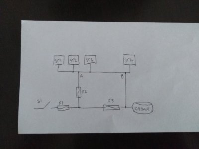
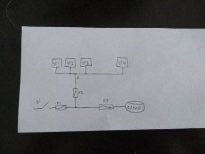
Look at this circuit, S1 is on your switch panel & switches on all your navigation electronics, shown here as your Seatalk instruments ST1 to 4 & your radar. The whole circuit is protected by fuse F1 at the switch panel. The Seatalk network has a power connection at A & is protected by its own fuse F2. The radar leg is protected by F3. No problems here.

email1695488389937_copy_640x480.jpg

Now you add a second supply to the Seatalk network at B like this...

email1695488410673_copy_640x480.jpg

You get a bad connection at F3. Now the radar's power is coming via the Seatalk network. You send it the command to start transmitting, it overloads fuse F2 which blows, & all your instruments go down. You replace F2, but that doesn't solve the problem.
 

RunAgroundHard

Well-known member
Joined
20 Aug 2022
Messages
2,247
Visit site
Timely thread this. I now have a peculiar situation on my Raymarine network.

I have Sea Talk NG connecting Evolution Autopilot (p70Rs control head ACU-400 EV1 Sensor Core EV1 Cabling kit). ST60s were stand alone and powered from at the switch board via their own switch and fuse. I then added Raymarine's STNG to ST converter for the ST60s with the Autohelm STNG cable connected into the white port, the Evolution end connected to the other white port and the ST60 cable into the yellow port. My ST60 instruments are always powered up when my Autohelm is on, irrespective of the Instruments switch on the panel.

Where do you think the power is coming from? Should I investigate further and change? Is it the same solution as PR's Post No 2? Or should I just disconnect the ST60s at the instrument panel.
 
Last edited:

PaulRainbow

Well-known member
Joined
16 May 2016
Messages
17,065
Location
Suffolk
Visit site
Timely thread this. I now have a peculiar situation on my Raymarine network.

I have Sea Talk NG connecting Evolution Autopilot (p70Rs control head ACU-400 EV1 Sensor Core EV1 Cabling kit). ST60s were stand alone and powered from at the switch board via their own switch and fuse. I then added Raymarine's STNG to ST converter for the ST60s with the Autohelm STNG cable connected into the white port, the Evolution end connected to the other white port and the ST60 cable into the yellow port. My ST60 instruments are always powered up when my Autohelm is on, irrespective of the Instruments switch on the panel.

Where do you think the power is coming from? Should I investigate further and change?
It could be taking the power from the ACU 400, turn the STNG power off, see page 23 of the manual.

Or, have you connected a power cable to the STNG network somewhere ?

Also, if i understand how you have connected the EVO together, it's incorrect. You should connect all of the EVO components and any other STNG devices together to form a network. You then connect one of the blue backbone ports on the network to one of the backbone ports on the ST-STNG converter.

You should only have one power connection, as above. If you use the ST power connection and that goes down, you lose the display for the AP. But if you power the STNG network from the AP and the ST network or the converter fail, you still have the AP.
 

RunAgroundHard

Well-known member
Joined
20 Aug 2022
Messages
2,247
Visit site
It could be taking the power from the ACU 400, turn the STNG power off, see page 23 of the manual.

Or, have you connected a power cable to the STNG network somewhere ?

Also, if i understand how you have connected the EVO together, it's incorrect. You should connect all of the EVO components and any other STNG devices together to form a network. You then connect one of the blue backbone ports on the network to one of the backbone ports on the ST-STNG converter.

You should only have one power connection, as above. If you use the ST power connection and that goes down, you lose the display for the AP. But if you power the STNG network from the AP and the ST network or the converter fail, you still have the AP.

Thanks, I will have to check on the boat. Recalling further from memory, what you have just written, about the other power supply, I did connect the ST1 - STNG Adaptor Kit - E22158 Red / Black white to the ST60 power supply cables.

Order of Installation (Pretty sure this is correct, not as my post)​

1. Evolution Autopilot (p70Rs control head ACU-400 EV1 Sensor Core EV1 Cabling kit. Connected to modified NECO motor. Stand alone system, using the Raymarine 5 x Way connector.
2. Later bought Axiom 12+ MFD and use a Raymarine STNG T-Piece Connector used to connect Evolution AP to Axiom 12+.
3. Lastly bought the ST1 - STNG Adaptor Kit and connected the ST60s to yellow port, power as described above, network blue and Autopilot spur (black / white) to the white port.

I am sure about the ST60 power supply, but not so sure about the blue backbone although I just followed the manuals. It is all Raymarine plugs and kit, nothing modified. Clearly I need to draw this out and get the facts.
 

PaulRainbow

Well-known member
Joined
16 May 2016
Messages
17,065
Location
Suffolk
Visit site
Thanks, I will have to check on the boat. Recalling further from memory, what you have just written, about the other power supply, I did connect the ST1 - STNG Adaptor Kit - E22158 Red / Black white to the ST60 power supply cables.

Order of Installation (Pretty sure this is correct, not as my post)​

1. Evolution Autopilot (p70Rs control head ACU-400 EV1 Sensor Core EV1 Cabling kit. Connected to modified NECO motor. Stand alone system, using the Raymarine 5 x Way connector.
2. Later bought Axiom 12+ MFD and use a Raymarine STNG T-Piece Connector used to connect Evolution AP to Axiom 12+.
3. Lastly bought the ST1 - STNG Adaptor Kit and connected the ST60s to yellow port, power as described above, network blue and Autopilot spur (black / white) to the white port.

I am sure about the ST60 power supply, but not so sure about the blue backbone although I just followed the manuals. It is all Raymarine plugs and kit, nothing modified. Clearly I need to draw this out and get the facts.
Sounds more like it should be, except for the power supplies. Just use the ST60, the ST-STNG (red/black or the ACU400. I prefer to power ST or STNG, depending what's on either network. Draw it out and start a new thread ?
 
Top