stu9000
Well-Known Member
Hi
I had a Rutland Wind generator but it stopped working in the January storms and I have not been able to get it going.
I bought two 115w solar panels which ive linked in parallel to a victron 75/15 mppt controller.
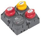
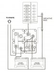
The old Marlec controller the wind genny fed into looked like this

Note the terminals for "batt1" and "batt2".
This was a nice feature that charged both the leisure and starter battery banks.
This is the new victron mppt controller

It only has one set of terminals for charging the battery which has me seeking advice on how to manage the starter and leisure battery banks.
Could I wire the leisure batteries to "load" and the starter to "batt"?
Or, should I just link the old wires for batt 1 (leisure) and batt 2 (starter) into the "batt" + and - on the Victron?
Would that mean the different banks are now linked (and that leaving the lights on could flatten the starter battery)?
Maybe I could fit a diode to prevent current reversal, but I really don't know what im talking about here.
A quick read suggests a voltage drop might be a drawback.
I could fit a one/two/both switch.
This would allow me to prioritize the charging to one bank or the other according to need.
Ideally, I would want the charge input to prioritise the starter battery until it reaches a certain point and then switch to charging the leisure bank.
There must be gizmo's or simple diode type stuff that does this.
What do other people do with their solar set up (don't say "buy a different controller")?
Thank you.
S
I had a Rutland Wind generator but it stopped working in the January storms and I have not been able to get it going.
I bought two 115w solar panels which ive linked in parallel to a victron 75/15 mppt controller.
The old Marlec controller the wind genny fed into looked like this
Note the terminals for "batt1" and "batt2".
This was a nice feature that charged both the leisure and starter battery banks.
This is the new victron mppt controller
It only has one set of terminals for charging the battery which has me seeking advice on how to manage the starter and leisure battery banks.
Could I wire the leisure batteries to "load" and the starter to "batt"?
Or, should I just link the old wires for batt 1 (leisure) and batt 2 (starter) into the "batt" + and - on the Victron?
Would that mean the different banks are now linked (and that leaving the lights on could flatten the starter battery)?
Maybe I could fit a diode to prevent current reversal, but I really don't know what im talking about here.
A quick read suggests a voltage drop might be a drawback.
I could fit a one/two/both switch.
This would allow me to prioritize the charging to one bank or the other according to need.
Ideally, I would want the charge input to prioritise the starter battery until it reaches a certain point and then switch to charging the leisure bank.
There must be gizmo's or simple diode type stuff that does this.
What do other people do with their solar set up (don't say "buy a different controller")?
Thank you.
S