Numpty SH VHF to Chart plotter question

mattonthesea

Well-Known Member
Joined
28 Nov 2009
Messages
1,522
Location
Bristol
ayearatsea.co.uk
On my old system I had an AIS engine with RS232 plug; so I had to have a RS232-USB adapter.

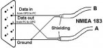
Now I have an SH GX2200 with bare wires. How do I work out the pin numbers to attach it? In the attached diagram if the wide edge is the top then are we looking at the pins towards us or is it pins away (as in if I was soldering from the back)? (I think that the GX only put out two pins and no ground - is tht right?)

EDIT OK so 10 mins later I looked it up - the wonders of G---gle! and I can't see how to delete this post
 

Attachments

  • SERIAL.jpg
    SERIAL.jpg
    11.6 KB · Views: 0
Last edited:
NMEA 0183 is specified as RS422, not RS232 (often incorrectly used), which means it's differential, so your new SH is correctly outputting Data+/Data- instead of Data/Gnd. You can often get away with connecting Data- to the ground pin on the RS232 input, and Data+ to the RX pin on your serial adapter. If not, you need a new RS422 serial to USB adapter from eBay for £5.

This should help: http://www.hardwarebook.info/Serial_(PC_9)
 
. You can often get away with connecting Data- to the ground pin on the RS232 input, and Data+ to the RX pin on your serial adapter.

Since you're looking for a voltage above ground on the data+ why bother connecting data- at all? Would connecting it somehow push data+ further positive with respect to ground?

I thought it was more normal for data+ to pin 2 & ground to pin 5.

Just stuck a scope on my 2100 which is single ended, voltage is about 4.7v above ground when sending.
 
Since you're looking for a voltage above ground on the data+ why bother connecting data- at all? Would connecting it somehow push data+ further positive with respect to ground?

I thought it was more normal for data+ to pin 2 & ground to pin 5.

There is no ground available, he's only got the two differential wires coming out of the radio. You could wire up a ground from somewhere, but it wouldn't necessarily be the right one, which could cause more harm than good (data ground is not always the same as the negative battery pole). Without a reference and only the Data+ connected, it would float and not work at all. So you can use the Data- of the differential signal. This is a dirty trick, but commonly used on boats with NMEA0183 wiring, where confusion between RS232 and RS422 reigns (even Raymarine did this - my Seatalk1 converter box outputs RS422 but its input is RS232). The clean solution is as I said to get a RS422 adapter, which will have Data+ and Data- pins (and doesn't require a ground, although may have a pin for it).

Looks like Matt already figured it out, just saw his edit on top.

OK, that makes sense, ta. I've never came across a bit of kit with nmea which didn't share data ground with power ground, didn't know such things exist.
 
I got to the boat and wired it all up. Result: zilch. Then I realised that the manual from SH says:

Gray NMEA DSC input pos - NMEA Pos input of GPS (for this read chartplotter)
Brown NMEA DSC output neg - NMEA Neg input of GPS

Does this mean I need to use the ground for the neg connection to brown? Or am I missing something? I'd not noticed that they were both inputs; so my wiring was assuming the Brown was output from pin 3

argh

You've confused the labels in what you've written down above.

The SH manual (page 18) is quite clear, you have two outputs, one at 4800 baud (Gray+/Brown-) and one at 38400 baud (Yellow+/White-). You choose either one of them, not both. You also have one input (Blue+/Green-), which you're presumably not using.

You now simply take your chosen outputs (typically the 38400 baud one, so Yellow+/White-) and wire it to your USB serial connector. The White- goes to GND and the Yellow+ goes to the receive pin (pin 2, labeled "From GPS to PC" on your diagram). Don't forget to tell the computer it's using 38400 baud (and 8 data bits, no parity and one stop bit, which should be the default). Juicy fresh NMEA sentences should now appear.
 
Don't forget to tell the computer it's using 38400 baud (and 8 data bits, no parity and one stop bit, which should be the default). Juicy fresh NMEA sentences should now appear.

And also go into the radio's set-up menu and set the NMEA speed to 34800.
 
Well I finally sorted it - but it was a bit complicated. For the benefit of anyone following I'll explain

Firstly, despite looking at several diagrams, the pin numbering was opposite to my understanding. What gave me the clue was that one diagram had male and female the same! Got the right pins and it worked. NMEA sentences appeared :-)

However, it stopped and started when I plugged the laptop charger in or off. So I took the alternative and used the 'grounding' method from the notes in the manual. Same thing happened but the other way around; the sentences disappeared when I unplugged the charger.

After a ponder I remembered that, for some unexplained reason, the electrics were all switched on the negative side. So when I plugged in the charger I was completing the ground contacts and that upset the NMEA circuit. This would also explain why my old, powered splitter and AIS engine fried the last RS422-USB adaptor!

So, a couple of days later, and a ton of spaghetti, I now have the switches on the positive side and it all works well. I even managed to pick up the AIS signal of a ferry in Bristol Harbour all of 400 metres away!

Thanks for the help
 
Top