Steeevo
New Member
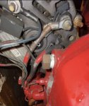
Hi. I have a lucas A127MT and How do i workout if it has combined alternator and starter wiring or seperate?
As i need to know for wiring up a new add a battery switch
As i need to know for wiring up a new add a battery switch


.jpg")