Inverter on board

Thank you Vic that explains it.
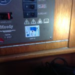
The inboard Gen (FP ) as an earth to one of the Keel bolt and once I buy and fitted the new inverter I will earth the case to that bolt .
Sorted ....
My reason for wanted to connect the inverter to the onboard power wiring was NOT to have multiple things running at the same time , but so I don't have an long extending wire running along the boat from the inverter to the galley which will be quite a way from the inverter plus it mean we can use any socket we like , plus I don't have to separate wires up things like the hot water heater to plug into the inverter.
Then there the risk of tripping over it, breaking it, plus its untidy .

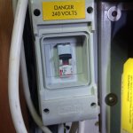
I assume that as the shore power once enter the boat goes through a RCD before it wired into a pole switch (Shore power/Gen/ Off) then into a second RCD on the main switch board before going to the AC bus bars . It be fine to just wire it into the shore power RCD ( without the income shore socket wired to it ) and let it use the same path as the shore power and Gen .
but before doing so I wanted to ask the knowledgable guys here for their advise .
Even if to some my question sound stupid to them.

Surly that be the best way forward then just start wiring stuff up.
Yes I appreciate that, but if you are going to connect the inverter to the existing shore power system it must have an output which has a "line" and an earthed "neutral", not two live conductors each at 115 volts relative to earth.
 
Yes I appreciate that, but if you are going to connect the inverter to the existing shore power system it must have an output which has a "line" and an earthed "neutral", not two live conductors each at 115 volts relative to earth.

More misleading and potentially dangerous stuff. Post#6 is what's relevant, bonding neutral and Earth at the inverter.
 
Yes I appreciate that, but if you are going to connect the inverter to the existing shore power system [,] it must have an output which has a "line" and an earthed "neutral", not two live conductors each at 115 volts relative to earth.

More misleading and potentially dangerous stuff. Post#6 is what's relevant, bonding neutral and Earth at the inverter.

Paul there is nothing misleading in Vic's post. the comment "earthed neutral" is the same as your statement bonding "neutral and earth"

The only moment is the lack of a commer where I added it . This has the meaning it ( the inverter) must have an output which has a "line" and a earthed neutral.


You are both saying the same thing but still not answering the OP's question

When you talk about an "Earth Connection" of the Inverter do you mean a connection to the metal case of the inverter.

Yes the case earth .

We all agree on the neutral / earth is connected at the inverter

So where does the case earth connect to

My question what safety benefit will that provide
 
Since the last posting I had a quick look .
The earth on the keel goes nowhere other end isn't connected and I can't imagine where is was once connected as there nothing near by and the end has a very tiny eye terminal.

The anode has six earth wires , three are from the metal fuel tank, fuel filler and a fuel filter , at the moment I can't find where the other three come from without ripping the boats to bits . Possibly from the E bus bar

Then FP Gen set L goes to the braker and from there LN straight to the pole switch , earth to the E bus bar
the shore power as soon as its enter the boat goes to a breaker from there LN to the pole switch earth to bus bar
The feeds from the pole L switchs goes to the main 240ac breaker then to the four other switch breakers / sockets, hot water heater, battery charges and Auxiliary, then to the L bus bar
The N goes to the N bus bar
Photo of the Gen breaker and the main board braker

More misleading and potentially dangerous stuff. Post#6 is what's relevant, bonding neutral and Earth at the inverter.

So before buying can you explain what I need to look for in a new inverter to be able to bond neutral and Earth together please .
 

Attachments

  • IMG_3373.JPG
    IMG_3373.JPG
    806.8 KB · Views: 19
  • IMG_3372.JPG
    IMG_3372.JPG
    817.8 KB · Views: 19
Is the case 'earth' the same as the DC return?

It's best to RTFM for the inverter, and if it doesn't tell you how to permanently install it, don't.

There's more than one way of installing AC in a boat, and it's best if you stick to one system, not install the inverter on a different scheme to the generator for instance.
You need to take care mixing the DC 0V return with the AC earth and avoid having either connected to the sea in multiple places through multiple routes, to avoid galvanic issues. This conflicts with the general 'need' to bond all AC earths together for safety reasons.
Likewise the drop on the DC 0V when the inverter is drawing a lot of current can cause issues.

There are a lot of inverters on the market which are basically not compatible with being installed on a leisure yacht, especially one with UK type 'Neutral' and single pole switching.
On a 'proper ship' the earth and neutral would probably not be directly bonded at the inverter.
It is a big subject and as PR implies, it cannot really safely be done by numbers over the internet.
 
When you buy a cheap "portable" inverter you have no idea what's in the case and no idea how it works. My advice is, if it has sockets on the front of it, it's not designed to be permanently fitted to the boats systems. It's portable and should only be used with equipment that can be plugged into the sockets, either directly, or by using an extension lead. A cable with a plug on one end and a fitted double socket would count as an extension lead, provided it is not connected to any of the boats systems, it has to be totally independent. Fixed appliances should not be connected to the inverter unless they are totally isolated from all other power sources. You should not connect a water heater, for instance. The inverter case Earth needs to be connected to the water, as i previously explained.

If you want a fixed installation, where all of the sockets and equipment onboard are supplied by the inverter, then fit an inverter designed for the purpose. This should be connected to a two pole changeover switch that is break before make. The neutral and Earth must be bonded at the inverter and the Earth must be connected to the water, as i previously explained. The battery charger and any other high current devices should be switched off when using the inverter, unless of course you want to heat the water, but this needs close monitoring. It's also possible to use a 4 pole changeover switch and use the 3rd and 4th poles to break the live feed to the charger.

If a generator is installed it should also be connected to the changeover switch. It should also have the neutral and Earth bonded at source and be Earthed to the same point as all other AC sources.
 
  • Like
Reactions: pvb
When you buy a cheap "portable" inverter you have no idea what's in the case and no idea how it works. My advice is, if it has sockets on the front of it, it's not designed to be permanently fitted to the boats systems. It's portable and should only be used with equipment that can be plugged into the sockets, either directly, or by using an extension lead. A cable with a plug on one end and a fitted double socket would count as an extension lead, provided it is not connected to any of the boats systems, it has to be totally independent. Fixed appliances should not be connected to the inverter unless they are totally isolated from all other power sources. You should not connect a water heater, for instance. The inverter case Earth needs to be connected to the water, as i previously explained.

If you want a fixed installation, where all of the sockets and equipment onboard are supplied by the inverter, then fit an inverter designed for the purpose. This should be connected to a two pole changeover switch that is break before make. The neutral and Earth must be bonded at the inverter and the Earth must be connected to the water, as i previously explained. The battery charger and any other high current devices should be switched off when using the inverter, unless of course you want to heat the water, but this needs close monitoring. It's also possible to use a 4 pole changeover switch and use the 3rd and 4th poles to break the live feed to the charger.

If a generator is installed it should also be connected to the changeover switch. It should also have the neutral and Earth bonded at source and be Earthed to the same point as all other AC sources.
Do you have any examples of an inverter you would recommend for a permanent installation? I have a portable cheapo which was originally for occasional use but now is connected pretty much permanently to at least one device, so thinking of going the whole way and connecting it to the whole boat’s AC system. I just have no experience of good or bad inverters (function and price). I really don’t need any more than 1000w.
 
Do you have any examples of an inverter you would recommend for a permanent installation? I have a portable cheapo which was originally for occasional use but now is connected pretty much permanently to at least one device, so thinking of going the whole way and connecting it to the whole boat’s AC system. I just have no experience of good or bad inverters (function and price). I really don’t need any more than 1000w.

You won't go wrong with Victron.
 
So before buying can you explain what I need to look for in a new inverter to be able to bond neutral and Earth together please .

My inverter has domestic socket outlets that you can simply plug any domestic main plug (13A square pin in the UK)

For a permanent installation I connected the earth pin to the neutral pin at the plug plugged into the inverter. I connected the lead (3 wire) L N and E wire) from the inverter plug/socket to my selector switch. then L and N went out from the switch to the onboard electrical wiring .

With my selector 3 position + off switch the output goes to the onboard electrical wiring .

The other 2 positions go to the shore power socket and to my mains generator.

The protective earth wires (Yellow/green) from all inputs go to a protective earth wire (yellow/green) to the onboard wiring Line to Brown, Neutral to Blue and Earth to Y/G wire then protective wire goes to the metal earthing point on my boat via a galvanic isolator in my cse the steel hull
 
When you buy a cheap "portable" inverter you have no idea what's in the case and no idea how it works. My advice is, if it has sockets on the front of it, it's not designed to be permanently fitted to the boats systems. It's portable and should only be used with equipment that can be plugged into the sockets, either directly, or by using an extension lead. A cable with a plug on one end and a fitted double socket would count as an extension lead, provided it is not connected to any of the boats systems, it has to be totally independent. Fixed appliances should not be connected to the inverter unless they are totally isolated from all other power sources. You should not connect a water heater, for instance. The inverter case Earth needs to be connected to the water, as i previously explained.

If you want a fixed installation, where all of the sockets and equipment onboard are supplied by the inverter, then fit an inverter designed for the purpose. This should be connected to a two pole changeover switch that is break before make. The neutral and Earth must be bonded at the inverter and the Earth must be connected to the water, as i previously explained. The battery charger and any other high current devices should be switched off when using the inverter, unless of course you want to heat the water, but this needs close monitoring. It's also possible to use a 4 pole changeover switch and use the 3rd and 4th poles to break the live feed to the charger.

If a generator is installed it should also be connected to the changeover switch. It should also have the neutral and Earth bonded at source and be Earthed to the same point as all other AC sources.

It's pretty clear what needs to do done now , thanks for your advise .
 
I see that there are good instructions for the installation of their inverters contained in the manuals and schematics of the wiring layout on the Victron website, which might be helpful for some.
Mastervolt also have good instructions on their website

Sterling Power inverters are neutral earth bonded and have easy to follow installation instructions
 
The answer to your original question is. " Yes, the earth terminal on the outside of the inverter must be earthed to your boat's main earthing point , which itself should have a connection to the water ... by an external earthing plate, a metal keel. or the hull in the case of a metal hull boat." ( I'm not happy about using the anodes. The anode wiring should be for the anodes only. Stray currents are bad enouh for anodes without connecting equipment to them that may cause stray currents)

Victron seem to agree with me (and the rest of the marine industry), this from them (full article here Boat electrical installations: combating seawater | Victron Energy):

Fig10.png


You still have not answered my two questions:

If the boat is GRP and has no external ground plane, where does one connect the Earth, if not the anode ?

If it's a metal hull and you connect it to the hull, is it not connected to the anodes, that are bolted to the hull ? The hull will be painted, so how is there continuity to the water, if not through the anodes ?
 
You still have not answered my two questions:

Let me answer these 2 qustions

If the boat is GRP and has no external ground plane, where does one connect the Earth, if not the anode ?

You are correct without a ground plane or other underwater metal the anode is the only way but this causes other issues as raised by Vic.

If any is going to use an anode as the only water connection there must be a GI between the earthing cable and the anode connection. There could be other underwater items line metal skin fittings or P bracket . These would be a better earth connection than an anode which could erode away to a point of beng ineffective as a earth/ground connection.


If it's a metal hull and you connect it to the hull, is it not connected to the anodes, that are bolted to the hull ? The hull will be painted, so how is there continuity to the water, if not through the anodes ?

Again my anodes bolts are welded to my steel hull but again it is very important to have a GI in the earth/ground/hull connection.

Thit steel hulls there are skin fittings of stainless steel that are in direct contact with the sea so it is not only an anode that this connection would be made

In Fig 12 of the article you posted has the GI in totally the wrong place as it it failed there would be no protective earth line from the shore power or any other mains supply device. With the onboard earth connector connected to the hull and the GI failed you may not even know that the GI has failed.

So in this case you would need a way of indication the incoming earth connection had failed.

You still have not answered the OP's Question "where to you connect the earthing point of the case of an inverter" and my question what safety does that connection provide.
 
Let me answer these 2 qustions

VICs made the claims, i'd like to hear his advice, he seems to think he knows better, but i very much doubt he'll answer.

You are correct without a ground plane or other underwater metal the anode is the only way but this causes other issues as raised by Vic.

What issues ? It's not a current carrying conductor.

If any is going to use an anode as the only water connection there must be a GI between the earthing cable and the anode connection. There could be other underwater items line metal skin fittings or P bracket . These would be a better earth connection than an anode which could erode away to a point of beng ineffective as a earth/ground connection.

No matter if the anode erodes, there's still a connect to the water through the bolts.

Why do you think an inverter needs a GI ? Shore power needs GI, no need for one for the inverter.

Again my anodes bolts are welded to my steel hull but again it is very important to have a GI in the earth/ground/hull connection.

Thit steel hulls there are skin fittings of stainless steel that are in direct contact with the sea so it is not only an anode that this connection would be made

No matter what else is in contact with the water, the anode still has electrical continuity with the AC PE

In Fig 12 of the article you posted has the GI in totally the wrong place as it it failed there would be no protective earth line from the shore power or any other mains supply device. With the onboard earth connector connected to the hull and the GI failed you may not even know that the GI has failed.

As you know better than Victron, i'd suggest you drop then an email.

You still have not answered the OP's Question "where to you connect the earthing point of the case of an inverter" and my question what safety does that connection provide.

I suggest you read my previous replies.

If the OP is still unclear he can ask for himself.
 
VICs made the claims, i'd like to hear his advice, he seems to think he knows better, but i very much doubt he'll answer.

I also doubt he will answer dur to you reaction that has been pointed out by others

What issues ? It's not a current carrying conductor.

An anode can be a carrying current if the is a fault and without a GI between the any leakage current can and does destroy the anode inno time


As you know better than Victron, i'd suggest you drop then an email.

In this instance I disagree with the article you posted in terms of the position of the GI in fig 12. This has been discussed before and I have no reason to contact Victron of anyone I have no dealings with.

I gave my reasons in my posting but you seem to believe the suppliers you recommend without looking at basic principles.

If the OP is still unclear he can ask for himself.

May he has but I cannot find any reference. There is still my question "what safety does that connection provide." To clarify connecting the case earth point on an inverter case to either a sea water ground plain or to the neural/earth point what does that protect against or don't you know or understand.

1611859728238.jpeg

There are 2 of the ways to connect a GI.

Which do you think is the best/safest
 
I also doubt he will answer dur to you reaction that has been pointed out by others

What are you referring to ?

In this instance I disagree with the article you posted in terms of the position of the GI in fig 12. This has been discussed before and I have no reason to contact Victron of anyone I have no dealings with.

I gave my reasons in my posting but you seem to believe the suppliers you recommend without looking at basic principles.

Of course, Victron won't know anything about basic principles.

May he has but I cannot find any reference. There is still my question "what safety does that connection provide." To clarify connecting the case earth point on an inverter case to either a sea water ground plain or to the neural/earth point what does that protect against or don't you know or understand.

I answered the OP in post #6

View attachment 108058

There are 2 of the ways to connect a GI.

Which do you think is the best/safest

No idea, your image is too small to see. But no matter, you'll know which is best without asking me. (or Victron)
 
I reckon PaulRainbow's comment in post 13 ("This is now too dangerous for me to be involved in.") was appropriate. I can't see any point in continuing these pointless arguments. If people want to fit inverters incorrectly, it's their problem ultimately.
 
Top