vas
Well-Known Member
Hello all,
following various threads discussing how to use Data USB sockets to charge devices like mobiles, tablets, cameras, etc onboard without resorting to inverters, I decided to gather all info together with links to bits you could use to accomplish this task.
Bearing in mind it took me a couple of years to get some decent results, I think it's worth going through the following.
Relevant threads are:
VIMAR-usb-connectors-24-gt-5V
Powered-USB-socket(s)-feeded-from-onboard-24V-circuit,
and finally in-line-12v-gt-220-40v-inverter
The problem I was trying to solve was how to charge all sorts of USB based devices without carrying various chargers AND having a big inverter running all the time. Further I have used the IDEA series of VIMAR throughout the boat and I bought a dozen DATA USB 1U sockets together with some assymetrical ones for polarised 24V (for fans, and a few other 24V devices). So 24V was available on each socket and it was a matter of dropping it down to 5V (usb standard) and routing it to the socket.
There are a series of different standards or protocols that various companies adhere to (or have developed and published). Generally acceptable ones ATM seem to be the 0.5A, 1.5A or 2.1A.
Getting into the details now, each USB socket has 4 connectors + - D+ and D-
+ and - is where you feed it with 5V (more on that later)
D+ and D- are the two data points that normally you do nothing (and you get f*ck all charging...)
So in order to get your devices to charge you can either use the USB Battery Charging Specification, Revision 1.2 (BC1.2) which gives you 1.5A and it's dead easy = you short D+ and D- or you start playing with voltage dividers (check the calculator halfway down the page) using resistors to drop and feed the D+ and D- with either 2V or 2.7V. TBH, it's only worth doing to get to 2.1A which worked with wifes Icrap.
2.0V/2.0V – low power (500mA) [absolutely pointless imho!]
2.0V/2.7V – Apple iPhone (1000mA/5-watt) [only worth if you have small 1A droppers, which you SHOULDN'T bother with...]
D+/D- shorted together – USB-IF BC 1.2 standard (1500mA) [easiest by far to implement providing decent current for most devices]
2.7V/2.0V – Apple iPad (2100mA/10-watt) [usefull for high end devices and I can only guess as time goes on more devices will demand more current!]
2.7V/2.7V – 12-watt (2400mA, possibly used by Blackberry) [didn't try it]
So go simple with a piece of wire and get 1.5A, or go fancy with 4 resistors and get 2.1A, up to you.
Now this means that you have to start with a dropper that has enough power to provide the right current for each case.
I initially got some Farnell droppers at 1A TRACO POWER TSR 1-2450 They are v.small and with a blob or hotglue you can stick them on the side of the USB socket. You do have to solder GND +IN and +OUT(5V) though.
Then I got the ones I've used in all high current setups which is:
DC-DC Adjustable Step-down Power supply voltage Converter Module Output 5V-35V +
Bigger in side, you need again to solder the ins and outs and you have to check with your voltometer and turn the brass tiny screw and get the voltage where you want! DONT MISS this step, else you may burn your device!
Pic below shows the 1A one when I was trying the various voltage dividers:

Sockets now look like this:
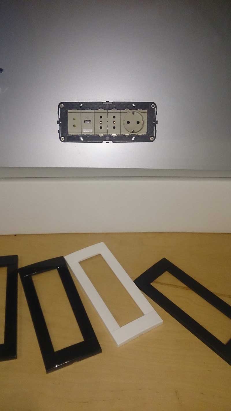
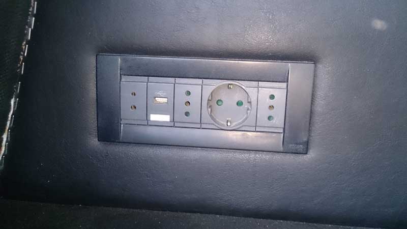
from left to right: 24V, USB (5V), 220V inverter, schuko (sp?) 220V generator, 220V inverter.
Hope it helps you sort out something avoiding drilling holes and fitting cigarette sockets all around the craft! And don't forget VIMAR and I guess all the other firms also have IPwhatever sockets for f/b, aft decks etc...
cheers
V.
following various threads discussing how to use Data USB sockets to charge devices like mobiles, tablets, cameras, etc onboard without resorting to inverters, I decided to gather all info together with links to bits you could use to accomplish this task.
Bearing in mind it took me a couple of years to get some decent results, I think it's worth going through the following.
Relevant threads are:
VIMAR-usb-connectors-24-gt-5V
Powered-USB-socket(s)-feeded-from-onboard-24V-circuit,
and finally in-line-12v-gt-220-40v-inverter
The problem I was trying to solve was how to charge all sorts of USB based devices without carrying various chargers AND having a big inverter running all the time. Further I have used the IDEA series of VIMAR throughout the boat and I bought a dozen DATA USB 1U sockets together with some assymetrical ones for polarised 24V (for fans, and a few other 24V devices). So 24V was available on each socket and it was a matter of dropping it down to 5V (usb standard) and routing it to the socket.
There are a series of different standards or protocols that various companies adhere to (or have developed and published). Generally acceptable ones ATM seem to be the 0.5A, 1.5A or 2.1A.
Getting into the details now, each USB socket has 4 connectors + - D+ and D-
+ and - is where you feed it with 5V (more on that later)
D+ and D- are the two data points that normally you do nothing (and you get f*ck all charging...)
So in order to get your devices to charge you can either use the USB Battery Charging Specification, Revision 1.2 (BC1.2) which gives you 1.5A and it's dead easy = you short D+ and D- or you start playing with voltage dividers (check the calculator halfway down the page) using resistors to drop and feed the D+ and D- with either 2V or 2.7V. TBH, it's only worth doing to get to 2.1A which worked with wifes Icrap.
2.0V/2.0V – low power (500mA) [absolutely pointless imho!]
2.0V/2.7V – Apple iPhone (1000mA/5-watt) [only worth if you have small 1A droppers, which you SHOULDN'T bother with...]
D+/D- shorted together – USB-IF BC 1.2 standard (1500mA) [easiest by far to implement providing decent current for most devices]
2.7V/2.0V – Apple iPad (2100mA/10-watt) [usefull for high end devices and I can only guess as time goes on more devices will demand more current!]
2.7V/2.7V – 12-watt (2400mA, possibly used by Blackberry) [didn't try it]
So go simple with a piece of wire and get 1.5A, or go fancy with 4 resistors and get 2.1A, up to you.
Now this means that you have to start with a dropper that has enough power to provide the right current for each case.
I initially got some Farnell droppers at 1A TRACO POWER TSR 1-2450 They are v.small and with a blob or hotglue you can stick them on the side of the USB socket. You do have to solder GND +IN and +OUT(5V) though.
Then I got the ones I've used in all high current setups which is:
DC-DC Adjustable Step-down Power supply voltage Converter Module Output 5V-35V +
Bigger in side, you need again to solder the ins and outs and you have to check with your voltometer and turn the brass tiny screw and get the voltage where you want! DONT MISS this step, else you may burn your device!
Pic below shows the 1A one when I was trying the various voltage dividers:
Sockets now look like this:
from left to right: 24V, USB (5V), 220V inverter, schuko (sp?) 220V generator, 220V inverter.
Hope it helps you sort out something avoiding drilling holes and fitting cigarette sockets all around the craft! And don't forget VIMAR and I guess all the other firms also have IPwhatever sockets for f/b, aft decks etc...
cheers
V.

