Fairlineboat
Member
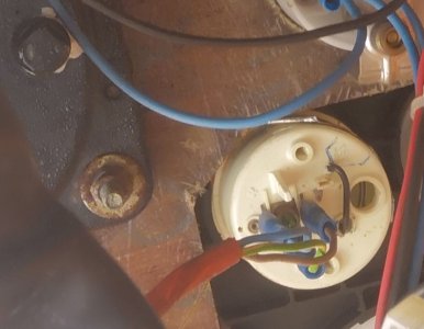
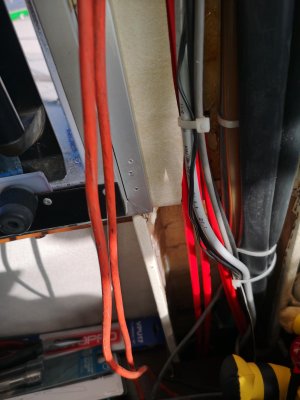
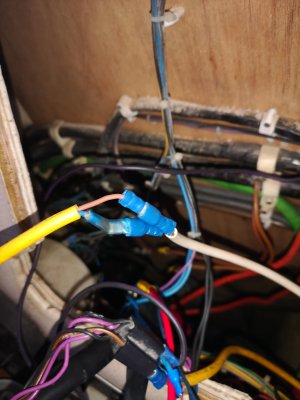
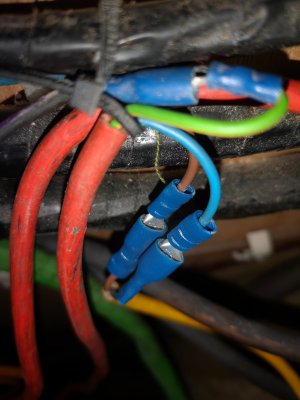
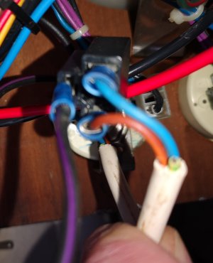
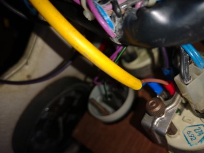
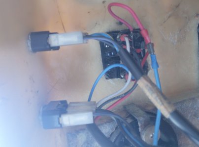
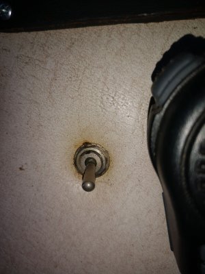
Hi all, So I was at the boat on Sat and took some pic which I have attached. The boat is 24v. So Pic 1 is the orange cable from flybridge to Helm. Pic 2 - 5 are cables connecting switch to dials. Pic 6 are cables connecting to a dial on the flybridge, Pic 7 is the switch and we have 2 on helm and 2 on flybridge, Pic 8 is another connection on helm. Pic 9 -10 is on the flybridge. Pic are cables connecting the switch and pic 10 is the orange cable connecting to a dial. It seems that it has been setup wrong as the orange cable is not connecting the switches. We have only 1 dial on the flybridge which is the oil dial. We have a rev counter and knots but they do not connected to the switches they have there on cables and they are working. Any help on this be great.


.jpg")
