AlexLbk
Active Member

I am not buying that .I'd expect to hear from Anthony (if he wants to chip in) but tbh sounds a bit OTT.
So you have a generator, a device tries to overload it, fair enough, FP generator obliges destructing itself? that sounds silly tbh!
FP system should be designed to limit available current and if over the limits crap out a message or whatever and turn off, going on to self-destruction mode is not the way to go!
if you haven't pointed this out you should and claim!
It’s what I thought , along the right track namely what’s changed ? Added electrotwackery.The suggestion is a charger .
If it’s not it will blow again .
You have to return everything to standard .Get rid of all the DIY electrotwackery you listed in your first post .
They all in my basic “ pressure “ apology for numbties inter act .
Back in 2014 my boat underwent a mini electrotwackery refit .I hired a boat sparky .He first did a survey to see what he had , what worked , and importantly what did not work .
He retro fitted €18 K s worth of Aircon .
Replaced a cockpit fridge was gobbling too much juice compromising the domestic bank , they go faulty that way and because still cold you think it’s ok .
Replaced the cook top with a marine 3 ring induction tailored to the geny .
Replaced the charger upping it from a 40 to 80 Ah .
The whole thing all of the above can be run off a 90 kg 3.5 kv air cooled Mase geny circa 2002 .
I was up for bigger new one you know €10-15 K worth of Onan or what ever .
Told me not needed .
I got him back once not for any of ^^^^ to instal a new TV aerial . He never invoiced me for that as was on another job in the marina .
I know there are a lot of techs on here and keen DIY ers .Blokes with certain tech training / qualifications etc etc .
Son did a masters in EEE .Electrical electronic engineering.
Told me ohm s law and his A level school stuff is all bollocks waaay over simplistic.
Even the movement of electrons in copper .There’s 30 + sub atomic particles going in all directions as well as the electrons .
This is why threads like this exist , in a kinda I don’t understand what’s going on the charger sucking power out the geny etc .
Something s ( my pressure analogy ) has back flowed up into the genys PCB boards .
I latched on this guy from Sunseeker .Fr .They run a huge charter fleet in the Cote d Azur + owners are demanding .He’s there first call for a break down .Spends a lot of time ripping out some OEM stuff and replacing with what he knows work .Be it air con , chargers , windless or what ever frustrates the crew / owners .Carry’s “ get you going “ spares on the van .
Eg after testing my charger which worked , it turned out it’s max output had decayed down from 40 to 4 Ah .
So all the lights , gauges to me looked pretty normal on this new boat to me .
We had a temp 100 Ah fitted there and then to carry on with the holiday ( spare on the van ) the new 80 came later .
Leaving it would have drained the batts esp the domestic while out and about .
Saturday , change over day is a 24 hr slog for him .
Quite ! J .See my post number #13......
I agree, but this is what I have unfortunately. At least it's beginning to make sense. The easy solutionI'd expect to hear from Anthony (if he wants to chip in) but tbh sounds a bit OTT.
So you have a generator, a device tries to overload it, fair enough, FP generator obliges destructing itself? that sounds silly tbh!
FP system should be designed to limit available current and if over the limits crap out a message or whatever and turn off, going on to self-destruction mode is not the way to go!
I heard you the first time and while in my years in IT we always asked what changed, I never allowed my staff to go backwards. If we did that all our computer systems including this website would still run on Wangs with COBOL as the underlying code with green terminal screens attached in a token ring network. I always moved forward and figured things out. So it's not that I think you are wrong, it is just not my approach. I didn't make the changes to the electrical system for fun; I did it to solve a set of specific issues: batteries not being charged properly by an alternator and stock charger not charging batteries quickly enough while at the dock. Both problems are solved now potentially at the expense of creating a new one. I wish there was a sparky around here that can guide me - I'm happy to pay for advice, I just don't want anyone to do any work for me except for cleaning and painting, so I try to pool information and figure things out hoping that there are people on this forum that are more experienced in generators than I am.It’s what I thought , along the right track namely what’s changed ? Added electrotwackery.The suggestion is a charger .
If it’s not it will blow again .
You have to return everything to standard .Get rid of all the DIY electrotwackery you listed in your first post .
They all in my basic “ pressure “ apology for numbties inter act .
Back in 2014 my boat underwent a mini electrotwackery refit .I hired a boat sparky .He first did a survey to see what he had , what worked , and importantly what did not work .
He retro fitted €18 K s worth of Aircon .
Replaced a cockpit fridge was gobbling too much juice compromising the domestic bank , they go faulty that way and because still cold you think it’s ok .
Replaced the cook top with a marine 3 ring induction tailored to the geny .
Replaced the charger upping it from a 40 to 80 Ah .
The whole thing all of the above can be run off a 90 kg 3.5 kv air cooled Mase geny circa 2002 .
I was up for bigger new one you know €10-15 K worth of Onan or what ever .
Told me not needed .
I got him back once not for any of ^^^^ to instal a new TV aerial . He never invoiced me for that as was on another job in the marina .
I know there are a lot of techs on here and keen DIY ers .Blokes with certain tech training / qualifications etc etc .
Son did a masters in EEE .Electrical electronic engineering.
Told me ohm s law and his A level school stuff is all bollocks waaay over simplistic.
Even the movement of electrons in copper .There’s 30 + sub atomic particles going in all directions as well as the electrons .
This is why threads like this exist , in a kinda I don’t understand what’s going on the charger sucking power out the geny etc .
Something s ( my pressure analogy ) has back flowed up into the genys PCB boards .
I latched on this guy from Sunseeker .Fr .They run a huge charter fleet in the Cote d Azur + owners are demanding .He’s there first call for a break down .Spends a lot of time ripping out some OEM stuff and replacing with what he knows work .Be it air con , chargers , windless or what ever frustrates the crew / owners .Carry’s “ get you going “ spares on the van .
Eg after testing my charger which worked , it turned out it’s max output had decayed down from 40 to 4 Ah .
So all the lights , gauges to me looked pretty normal on this new boat to me .
We had a temp 100 Ah fitted there and then to carry on with the holiday ( spare on the van ) the new 80 came later .
Leaving it would have drained the batts esp the domestic while out and about .
Saturday , change over day is a 24 hr slog for him .
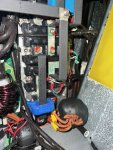
I struggle to see how a 3kW charger can overload a 15kW generator. There should be an generator/inverter output breaker to stop overload damaging the unit. I would also be surprised if there is not some sort of under voltage and under frequency protection inbuilt into the inverter to self protect during an overload.So after bothering FP for the past week, we are finally getting somewhere and it seems like the charger might have caused the whole thing to blow up and this was installed recently. The charger is a Xantrex Freedom XC pro marine 3000. FP seems to think that settings on the charger drew too much current from the generator causing the IGBT to fail and blow the capacitors, the capacitors then sent too much voltage to the icontrol board blowing that up as well. I have already ordered the replacement board from Spain, replaced the two blown capacitors, and ordered an additional 12 to replace them all and have two spares. The next question is how to locate and test IGBTs in the PMGI. I have asked FP for that information, but didn't hear any excitement on the prospect, so if the group has any ideas what I should be testing - I would really appreciate it. Next step for me is to figure which charger settings need to be updated on Xantrex to avoid this going forward.
Xantrex support stated they have no specific settings for generators. The only thing they have suggested is to possibly lower the charge voltage, which would have made sense if the generator failed immediately when the charger turned on and went to bulk mode. It failed after an hour of running, I can probably pull the data if needed, but based on prior experience charger went to float after 10 minutes or so since the batteries were 90+ % charged. Again all the data is logged, I didn't yet write retrieval interfaces though so pulling the data is a pain, but if anything is needed I can pull it with some effort. BTW, charger runs all day every day on shore power with no issues. The charger has an control panel and bluetooth app with all the settings. The settings match the batteries down to manufacturer spec.I am not buying that .
Charger works with what’s it gets fed .Wether that’s a geny in various stages of dishing out its AC or dodgy variable shore power .They arn’t fussy .They gobble up AC and throw out bat charging DC .
You do have dip switches on the outlets ( or just plane switches) to tell it what type of batteries it hooked to .
Thats not the issue here .I think unless the Op can confirm he hasn’t tuned it to the battery banks .New + old .
Q to Op are there any dip switches by the power in connection from geny / shore power ?
Does it indeed ( very unlikely imho ) need to know stuff like what type of geny .Bear in mind it’s mostly at the dock eating shore power juice which is not quite the same flavour as the geny juice .Nearly but not previously the same .
I already ordered the new pcb and will replace all the capacitors, not just the two blown ones. I would really appreciate any help in testing IGBTs. If they are bad, I will swap them out as well. Again FP believes that a failure in IGBT caused the capacitors to blow and a subsequent restart with a blown capacitor caused the icontrol board to burn. I am just relaying what I have been told - no opinions.Totally agree, no way a relatively small load should overload the generator. With all that electronics there should be more than adequate protection.
Do you want to test the IGBTs? I can help with that but would advise this is beyond a DIY fix because of all the damage to the pcb etc.
We can get the power components working but it looks like there is extensive damage to some of the control circuits and that could destroy any replaced power devices.
Crap design I think, I worked on some inverter power supplies back in the 1980s. lots of over voltage and over current protection crowbar circuits but they caused so many failures we stopped soaking the supplies overnight due to them causing fires.
I am nursing an older Fisher Panda generator, the chances of replacing it it with another Fisher Panda are really zero.
Let me know if you really want further testing details.
") Thanks in advance.
Thanks in advance.


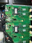
Wrist strap is not a problem. Do I need to resolder those resistors in the picture in order to test?You must remove the IGBTs from the circuit board to test them because the circuitry will affect the measurements. Be aware they are very static sensitive, the gate structure can be weakened if everything is not suitably grounded. This is where it starts to get a bit more involved, I would always wear a wrist strap grounded via a 1 megohm resistor when working with IGBTs, they are very sensitive. Also the pcb may be multilayered so you may need a desoldering iron to suit.
Hello, no, the resistors must be removed.Wrist strap is not a problem. Do I need to resolder those resistors in the picture in order to test?