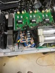
Fischer panda generator isssues

Portofino

Well-known member
Joined
10 Apr 2011
Messages
12,174
Location
Boat- Western Med
Visit site
Going back to what’s changed since it ran well , before you “turned it on at sea “ running .

I don’t believe in coincidences or bad luck with new kit or older tried + tested over years kit .

Something has or was changed before it went “ bang “ ….Electrically over all in the boat not just the geny .

What did you do last ? If you can’t arrive at a diagnosis and hope just throwing parts a the problem it’s gonna repeat .

You might or others interested in this thread find this helpful he mentions capacitor going “bang “ ?


ARE

Member
Joined
12 Jul 2010
Messages
218
Location
Norfolk
Visit site
This type of capacitor regulation (shown in video) is completely different to the way a FP15000i works, the above is to regulate a traditional copper wound AC generator. The capacitors inside the FP15000i inverter are for supporting motor starting surge current, that’s why there is 12 of them.
 

Portofino

Well-known member
Joined
10 Apr 2011
Messages
12,174
Location
Boat- Western Med
Visit site
This type of capacitor regulation (shown in video) is completely different to the way a FP15000i works, the above is to regulate a traditional copper wound AC generator. The capacitors inside the FP15000i inverter are for supporting motor starting surge current, that’s why there is 12 of them.
The salient point is what’s changed before the thing went bang ?
And parts throwing with out a diagnosis rarely works .

Somethings caused the electrotwackery in case the inverter in the geny ( not the boats 12to AC ) as you correctly say ( doesn’t really matter exactly what it is) to go
“ bang “.
What could it be ?
My$ are on recent electrotwackery changes .

I mean could power from the new boats inverter have upset the geny ? My basic pressure analogy.Restricted flow out though it blew capacitors .

We don’t know what’s was on / off when the geny was started running or if its all been connected properly in the first place .
 
Last edited:

AlexLbk

Member
Joined
4 Jul 2022
Messages
56
Location
New Jersey
Visit site
The salient point is what’s changed before the thing went bang ?
And parts throwing with out a diagnosis rarely works .

Somethings caused the electrotwackery in case the inverter in the geny ( not the boats 12to AC ) as you correctly say ( doesn’t really matter exactly what it is) to go
“ bang “.
What could it be ?
My$ are on recent electrotwackery changes .

I mean could power from the new boats inverter have upset the geny ? My basic pressure analogy.Restricted flow out though it blew capacitors .

We don’t know what’s was on / off when the geny was started running or if its all been connected properly in the first place .

Generator ran on the way there for a couple of hours, it blew up after an hour or so on the way back. We ran the usual things: 3 ACs as opposed to 4, a few minutes of microwave time and chargers. Most of the loads are 12V. The generator is really only used for cooking or AC. The only thing that got affected besides the generator was the GFCI connector I bought at home depot last year. All the german outlets survived. Everything else is working as before. It was hot, but then again we left Florida 2 years ago in the end of August - it was a lot hotter there. I don't know whether the caps will address the issue - Fischer Panda seems to think so and they weren't surprised that they failed either. Inverter is not connected to the mains when generator is running - the switch prevents that, when inverter is enabled it only feeds part of the panel - just receptacles really - so I can charge my laptop and run a kettle - that's all it does when it's on and it's almost never on since I don't really need it. It was purchased for the charger, inverter was connected just because it's there. When the switch is in shore/generator position, the inverter is connected to nothing and inverter panel reflects no load. I can't tell you much more than that.
If you have any ideas on how to diagnose "electrotwackery", I'm game.
 

AlexLbk

Member
Joined
4 Jul 2022
Messages
56
Location
New Jersey
Visit site
Why not fit a surge protector after the gen output.
Not a bad idea - I have done whole house surge supressors, not sure if they will survive the boat though. Also in a house I split phases on the panel, here they are already split, so I will need one for each phase. Anyway, something to think about.
 

AlexLbk

Member
Joined
4 Jul 2022
Messages
56
Location
New Jersey
Visit site
This type of capacitor regulation (shown in video) is completely different to the way a FP15000i works, the above is to regulate a traditional copper wound AC generator. The capacitors inside the FP15000i inverter are for supporting motor starting surge current, that’s why there is 12 of them.
Didn’t notice this post. I thought so too, but wasn’t sure. So if these capacitors control input from the magneto before going to the three rectifiers then how can the inverter that is connected to the output side can possibly affect anything on the input side? That said I just toned the wire that was going out of the generator inverter while the inverter charge was on and enabled. I got .2V AC at the leads.
 

Portofino

Well-known member
Joined
10 Apr 2011
Messages
12,174
Location
Boat- Western Med
Visit site
Generator ran on the way there for a couple of hours, it blew up after an hour or so on the way back. We ran the usual things: 3 ACs as opposed to 4, a few minutes of microwave time and chargers. Most of the loads are 12V. The generator is really only used for cooking or AC. The only thing that got affected besides the generator was the GFCI connector I bought at home depot last year. All the german outlets survived. Everything else is working as before. It was hot, but then again we left Florida 2 years ago in the end of August - it was a lot hotter there. I don't know whether the caps will address the issue - Fischer Panda seems to think so and they weren't surprised that they failed either. Inverter is not connected to the mains when generator is running - the switch prevents that, when inverter is enabled it only feeds part of the panel - just receptacles really - so I can charge my laptop and run a kettle - that's all it does when it's on and it's almost never on since I don't really need it. It was purchased for the charger, inverter was connected just because it's there. When the switch is in shore/generator position, the inverter is connected to nothing and inverter panel reflects no load. I can't tell you much more than that.
If you have any ideas on how to diagnose "electrotwackery", I'm game.
The classic way is return everything back to OEM , then change bits one by one and test in between .
 

Bran

Active member
Joined
27 Mar 2012
Messages
446
Location
Bedfordshire and Surrey
Visit site
Merson are your nearest distributor of F and T capacitors:
Home page | Mersen Electrical Power: Fuses, Surge Protective Devices, Cooling & Bus Bars
This make of capacitors are really good quality, so something else is causing them to fail so you will need to trace that issue.
If Mersin won’t help you then find a good HiFi audio components dealer as F and T are used in high end audio systems.


you can get the part number for the capacitor from the data sheet below:
https://www.ftcap.de/fileadmin/user...ondensatoren/webboxen/Gewindeanschluss/GM.pdf

From your details so far I think the part number is: 22225040080:
9D8E1CBF-15E0-42F1-8F8B-17D6293C0DF6.jpeg

This reminded me of my days working in electronic test and calibration, we had 400v versions of that capacitor and would charge them up and throw them to each other. You had to make sure you caught them without touching the terminals, shocking!
 

ARE

Member
Joined
12 Jul 2010
Messages
218
Location
Norfolk
Visit site
Didn’t notice this post. I thought so too, but wasn’t sure. So if these capacitors control input from the magneto before going to the three rectifiers then how can the inverter that is connected to the output side can possibly affect anything on the input side? That said I just toned the wire that was going out of the generator inverter while the inverter charge was on and enabled. I got .2V AC at the leads.
From my understanding these capacitors store the power between the PMG generator and the inverter, when you demand a high power load (ie motor starting) these capacitors release their stored power while the variable speed PMG picks up speed.
 

vas

Well-known member
Joined
21 Jun 2011
Messages
7,933
Location
Volos-Athens
Visit site
Anthony,

this means that even with a few (or all!) of these capacitors out of action, generator/inverter combo should be producing the required Voltage... so something else is behind all that :-(
 

ARE

Member
Joined
12 Jul 2010
Messages
218
Location
Norfolk
Visit site
Didn’t notice this post. I thought so too, but wasn’t sure. So if these capacitors control input from the magneto before going to the three rectifiers then how can the inverter that is connected to the output side can possibly affect anything on the input side? That said I just toned the wire that was going out of the generator inverter while the inverter charge was on and enabled. I got .2V AC at the leads.
From my understanding these capacitors store the power between the PMG generator and the inverter, when you demand a high power load (ie motor starting) these capacitors release their stored power while the variable speed PMG picks up speed.
Anthony,

this means that even with a few (or all!) of these capacitors out of action, generator/inverter combo should be producing the required Voltage... so something else is behind all that :-(
no, because all the power between the generator and inverter passes through the capacitors. If the capacitors are faulty you will not get power to the inverter. I don’t believe the generator produces 230v 50hz, normally on this type of variable speed generator the output is something like 300v 300hz and the inverter converts this into 230v 50hz.
 
  • Like
Reactions: vas

Croftie

Active member
Joined
19 May 2015
Messages
736
Visit site
I have low knowledge of electronics but if the gen produces 300v why are 250v capacitors fitted are they under speced?
 

Croftie

Active member
Joined
19 May 2015
Messages
736
Visit site
I guess they are in series so some of them "share" the Voltage produced amongst them...
Thanks Vas, I can undestand that. Electrics (12v, 240v 3 phase etc) I am fine with but electronics - black art if more than very basic.
 

Bran

Active member
Joined
27 Mar 2012
Messages
446
Location
Bedfordshire and Surrey
Visit site
From my understanding these capacitors store the power between the PMG generator and the inverter, when you demand a high power load (ie motor starting) these capacitors release their stored power while the variable speed PMG picks up speed.
Those capacitors are electrolytic so are polarised, ie they must be supplied a dc supply. The output of the generator itself is three phase ac in the order of 300-400 Hz as ARE mentioned, so the capacitors must be after some rectification diodes in the pmg box. As I mentioned before F and T are considered some of the best quality components so something else is causing them to fail. Without a circuit diagram all you can check is that all connections are very secure between the generator and pmg box, maybe check the rectifiers. If you can take some photos of the internals of the pmg box maybe we can advise a bit more, please be careful, there’s a lot of stored energy in those capacitors and if the discharge resistors have a fault you could get a nasty surprise.
 

AlexLbk

Member
Joined
4 Jul 2022
Messages
56
Location
New Jersey
Visit site
I will take some pictures of the boards in the pmgi box, but they look pretty much virgin. Both capacitors were replaced, everything was put back as it was. The generator engine starts, however the panel still shows starting, rpm are at 0. Then the generator shuts down with failure to start. It obviously starts, but it lost an ability to see that somehow. There are 3 set of boards: next to the engine, pgns box and a control panel. I was able to see 180 volts on each of the inbound phases. Outbound phases have no voltage. I hear pmgi fans turn on when start is pressed on the control panel, otherwise pmgi lights don’t light up. Not sure what else to do beyond sending all the boards to Fischer panda.
 

AlexLbk

Member
Joined
4 Jul 2022
Messages
56
Location
New Jersey
Visit site
spoke to giacher panda DE this morning. They have identified possible issues as a control board on the inverter (couldn’t find this board) or transistors (I assume they meant rectifiers). I decide to ship all the electrical components to their Florida office. When I pulled the icontrol board I found what blew up and it wasn’t the capacitor. The microchip on that board simply melted, one side of the chip is literally gone. This would certainly explain why the panel doesn’t detect engine rpm. Still don’t know what specifically happened and if the board went first and blew the capacitors or the capacitors went first and killed the board. I think it’s the later since I heard the board pop.
 

Bran

Active member
Joined
27 Mar 2012
Messages
446
Location
Bedfordshire and Surrey
Visit site
It’s very likely that Fisher Panda just buy in the complete pmgi units and don’t get too involved in component replacement. I would bet that FP don’t even have individual circuit diagrams for the pcbs, just module connection layouts.
You don’t really have a choice, it has to be replaced and tested by FP or their pmgi supplier. Once out of warranty I would have done the same and opened up the unit, it’s very frustrating these days that you cannot diy fix even if you have electronics and electrical training.
 
Top