nigelmercier
RIP
- Joined
- 20 Jun 2007
- Messages
- 16,234
- Location
- Live in Kent, boat in Canary Islands
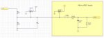
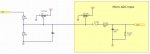
... Not a lot of chance of that in your circuit since there is a 300k resistor in line as well...
Not a lot of chance even with my more reasonable values for the resistors. In normal circumstances the diode does nothing, only when there is a spike will it conduct.


")