Malabarista
Well-Known Member
Thanks guys trying to get a hang of the laptop first and the the diagram ?
Thanks BirdseyeGot to say Dave that it sounds to me like you are tackling a job outside your skill set and capabilities, and would be better paying for a leccy. I have seen a boat that got a dead short at sea with matching fire and it wasnt funny.
It depends on where things are physically whether there's any real gain.Just been reading on a marine how to site that i should put the alternator live feed in the house battery side to help the cyrix ( vsr) is this better than on the engine battery side?
Just been reading on a marine how to site that i should put the alternator live feed in the house battery side to help the cyrix ( vsr) is this better than on the engine battery side?
Thanks for helping me out with this. I am working on a new draft ?It depends on where things are physically whether there's any real gain.
If the house batteries are a long way from the engine, then it's a lot of wire.
If it can be done with little extra wire and few connections, it does help, as the house battery should be taking much more charge than the engine battery. At say 60A, even a few milliohms make a difference.
OTOH, for relability, simplicity and ease of future people knowing what's what, keeping the engine/alt/starter/battery 'module' self contained and easy to understand has its merits.
Imagine if damage happens, it's good to be able to run a minimal system with everything else isolated.
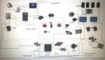
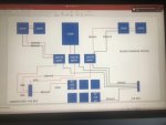
I think you need a better diagram. Consider that one day you might want to explain it to a stranger over the phone.
Frankly it's hard to follow on my PC, it looks like too many connections, junctions, pointless breakers and unclear functionality.
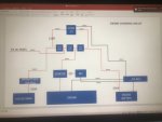
To be completely clear the negative 12vdc bus connects to the engine chassis,the consumer unit earth bar ( inside the 240v plastic box) and the anode yes?
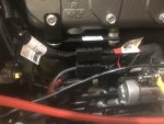
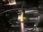
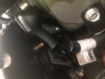
The alternator and starter are already wired together from what it look like ( please see photos).
")
From the unswitched pos busbar the two bilge pumps are fused separately ( 15 & 5 amp) at the battery end and again at their respective switch panels. Less than two metres of the 2.5mm cable you recommended when we met.
I already bought the sterling charger unfortunately and it has been working for 2 years ( on a much smaller bank).
I have taken your advice and ditched one pair of the trojans although i am tempted to use them as an engine starter battery. This is nothing to do with CCA versus AH but more to do with woodworking. I built a rather lovely battery bay to house the full eight ?.
I also bought two Victron MPPT 100/30 controllers in the interests of redundancy and shading with each having a max input of 440W. Does this mean I cannot use both. My 350W big panel on the hardtop also came with a controller ( PWM) which i may take as a spare in case i blow something up!
So my plan was to join the 2 150W panels on the Port pushpit rail in series to one controller and Stbd pushpit rails to the other to minimise the effects of shading from the mizzen boom. Am i being daft again?


Hi PaulBig fuse at battery to protect 35mm cable to busbar is fine, individual pump fuses also fine, but you will have stepped down in cable size from the busbar to the fuse panel, this cable is now unprotected.
Thanks PaulNo problem with the cable size, for those loads. But, it is unfused. The main battery fuse would be unlikely to blow if that cable or the internal gubbins of the fuse box shorted out. As it's only 300mm long, provided it can absolutely 100% be impossible to short the cable, you could possibly argue that a fuse isn't needed.
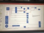
A bit late to this perhaps, but I think that the 3 way switch in your AC circuit diagram should be double pole, that is switch both line and neutral.After the Christmas shenanigans and much research I think I am ready (once again) to expose myself as an electrical numpty. I know I am asking a lot but if anyone cares to have look and comment on my efforts I would be extremely grateful. Thanks
")
")