geegrrl
Member
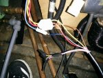
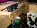
I got the Eberspacher Easystart Timer in order to replace the Mini Timer. The Mini has no fault diagnosis or reset capabilities. I was hoping just to slot the Easystart in place of the Mini. The problem is the Mini Timer only seems to utilize 3 wires - red, yellow and brown. However I can follow the wiring loom down from the Mini-Timer and see there is an unconnected blue and white wire (for diagnostics). So that gives a total of 4 wires. But the Easystart Timer has 8 wires (red, yellow, brown, grey, violet, blue&white, grey&black, brown&yellow, white&red, brown&white). I connected all the wires I could (red, yellow, brown, blue&white). I replaced the 10A main fuse and the unit light comes on and says "INIT". So far so good. Then I get an error telling me there is "No Signal". The manual tells me this means there is "No communication". It tellsme to check the fuse, voltage supply or the wiring. The 10A blade fuse looks good to my eye. The voltage supply showed a proper 12 something volts. So what is wrong with the wiring? I can see no other wires other than the red, yellow, brown, blue&white which is available to the current Mini Timer. So I'm scratchin' my head. Any ideas? Attached are some pix.