Fire99
Well-Known Member
Hi all,
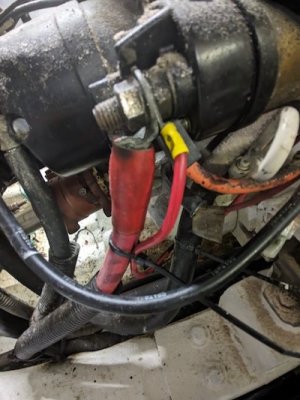
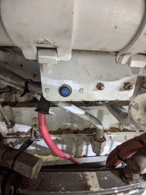
I've started to wade into my boat's DC electrics as there appear (from old paperwork I've found) to be some bad electrical decisions made, including bridging the house and starter batteries together, due to a lazy starter motor on one of the engines.
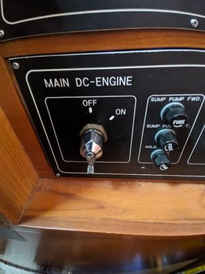
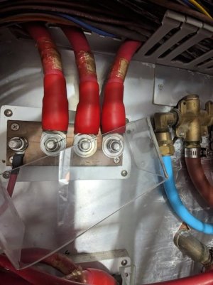
Whilst investigating I've found that one of the 240v charger (Sterling Pro Charge Ultra) outputs runs from the charger directly to the supply side of the DC Engine Isolator switch. Which means if the shore power is connected and the charger breaker is on, the engines are receiving 12v from both the batteries and the charger which my rusty mind would say is an odd decision.
Can anyone throw any light on why in normal practice anyone would do this? Many thanks..
I've started to wade into my boat's DC electrics as there appear (from old paperwork I've found) to be some bad electrical decisions made, including bridging the house and starter batteries together, due to a lazy starter motor on one of the engines.
Whilst investigating I've found that one of the 240v charger (Sterling Pro Charge Ultra) outputs runs from the charger directly to the supply side of the DC Engine Isolator switch. Which means if the shore power is connected and the charger breaker is on, the engines are receiving 12v from both the batteries and the charger which my rusty mind would say is an odd decision.
Can anyone throw any light on why in normal practice anyone would do this? Many thanks..
Last edited: