UK-WOOZY
Well-Known Member
that might explain why i had to have the head inlet/outlet through hulls / cocks replaced when i had all the seacocks checked when i bought the boat. rest have been check and deemed good.


Unfortunately it won't make any difference. To quote Viv Cox from a previous thread "Skin fittings have only been available in DZR for the past two or three years and all are marked CR, although I believe other markings are used in Australia. If the fitting is old and not marked there is every likelihood that it is brass."unclear if to remove the earth cabling still
unclear if to remove the earth cabling still
excellent advise again, appreciated. i think ill leave the cables on the seacocks in situ for now and looking into it further. i really want to test the boat out before the years over and it will come out again in early jan till the season starts again.
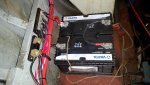
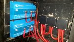
im still unclear how the alternator is connected though, how do i tell how the alternator is connected. im sure the panels are separate now except the battery tester. but would these devices be good to use if i want to separate the batteries. and what type cabling should i use. thanks
http://www.cactusnav.com/bluesea-mi...dYEIiAEZfp00-sOYip3gUcCfS24ZA9vRoCWGQQAvD_BwE
and
https://www.cclcomponents.com/victr...BdHIrvL1QoFgON06q6LniTJc8qSKGg3BoCE7wQAvD_BwE
next year i will want to add another house battery, how would that work along side those kits?
boll*cks, sorry i just ordered the add another battery kit as it seemed the simplest to wire up. its already shipped.