Cockpit repeater for SH180i

PuffTheMagicDragon

Well-Known Member
Joined
16 May 2001
Messages
14,403
Visit site
My present cockpit instrumentation consist of a NEXUS SeaData and GARMIN GMi20 instrument that is fed from a wireless Wind transducer. They communicate with each other via a Garmin GND10 bridge that interfaces the NMEA 0183 data from the Nexus bits with the NMEA 2000 bus that is used by the Garmin parts.

I have been told that connecting the brown and the green wires (TxA+ and TxB-) from the SH180i chart plotter (at the chart table) to the GMi20 0183 input (RxA+ and RxB-) would allow me to see GPS data in the cockpit. I have tried this but after a few minutes the GMi20 goes blank. At first I thought that there might be some setting that is reachable through software. I therefore linked my laptop to the GND10 bridge (via a USB cable) and ran Nexus Race. Wind, depth, water speed and other info that does not involve GPS all showed up accurately on the laptop. However, SOG and POS were showing "not available". Strangely enough the GMi20 did not go blank while the laptop was still connected.

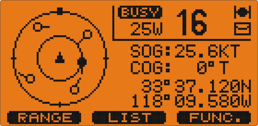
My question is this: Is it really possible to use the GMi20 as a 'repeater' for the GPS data from a SH180i chart plotter? All I am interested in would basically be POS, SOG and COG. My feeling is that the SH180i does not send out any data that can be used for this purpose but I am rather like a blind man with a broken white stick in these matters.

Any ideas please?
 
the 180 does output ok, mine feeds a DSC/AIS radio just fine

Yes, it does output those, but I don't think that it outputs any GPS dependent data like COG, SOG or POS... not as far as I can see anyway, which is why I asked.

As far as I can tell from the handbook the output from Port 1 (brown wire) is only GGA, GLL, RMC, DBT, DPT MTW, VHW and XTE sentences... whatever that may mean. :(
 
Sorry I should have been clearer, the AIS/Radio displays COG POS and SOG from the CP180 using those sentences

GX2100_AIS-Target.jpg
 
Last edited:
As far as I can tell from the handbook the output from Port 1 (brown wire) is only GGA, GLL, RMC, DBT, DPT MTW, VHW and XTE sentences... whatever that may mean. :(

Not going to look up the exact contents of those sentences, but they should contain more than enough information between them for simple COG and SOG (not sure why you also want position in the cockpit, are you going to be using dividers on a chart up there when you own a plotter?). Google NMEA sentences if you want to know what's in them, there are a couple of well-known lists out there.

Do the instruments you're trying to connect to have a debug mode in which they display what's coming in via NMEA? Many do....


Pete
 
... the brown and the green wires (TxA+ and TxB-) from the SH180i chart plotter (at the chart table) to the GMi20 0183 input (RxA+ and RxB-)
First problem is that the SH is not sending TxA+ and TxB-, it is sending TxA and GND. Most instruments will accept this, but you need to check if the GM does.
Second problem, was the speed set at 4800 on the receiving instrument?
 
First problem is that the SH is not sending TxA+ and TxB-, it is sending TxA and GND. Most instruments will accept this, but you need to check if the GM does.
Second problem, was the speed set at 4800 on the receiving instrument?

According to the Garmin wiring instructions (I was trying to take a photo of the diagram from a pdf file... no success) the GM does. The Rx/A (+) goes to the Tx on the 0183 device (brown wire) while the Rx/B (-) goes to the other device's data ground (green wire) so I think that so far it is 'according to the instructions'.
Regarding the 4800 I would imagine that the speed would be OK because they are managing to 'talk' to each other via the GND10 bridge, NMEA 0183 to NMEA 2000.

What is now bugging me is the fact that GGA and GLL should be giving me what I need... but aren't!
 
they should contain more than enough information between them for simple COG and SOG

Presumably they should because the GGA and the GLL would be giving the position.


Do the instruments you're trying to connect to have a debug mode in which they display what's coming in via NMEA? Many do....
Pete

I'm afraid I haven't a clue!
 
I don't have the manual to hand, but the CP180 has a setting for what sentences appear on the output ports. I would imagine that you could also loop back into an input and check it on the data display, as #10 above.

Yes, I can try that. However, further thinking about what you said in post #7 that the SH180 has only one Tx output I am now considering whether joining the power ground to the data ground would solve the problem. The diagram that I was trying to copy from the installation 'instructions' for the Garmin GMi20 (unsuccessfully, because the pdf file is copy-protected) shows this as having the data ground and the power ground from the NMEA0183 device going to the Garmin's Rx/(-) while the 0183's Tx goes to the Garmin's Rx/(+).

Do you think that doing this could damage the SH180? Would it solve the communication problem?
 
... further thinking about what you said in post #7 that the SH180 has only one Tx output I am now considering whether joining the power ground to the data ground would solve the problem...

The 3 output ports deliver their signals between NMEA ground (pin 3, Green) and the port output:
Port 1: pin 5, Brown
Port 2: pin 7, White
Port 3: pin 8, Yellow

Connecting NMEA ground to power ground is not advised, or necessary.
 
The 3 output ports deliver their signals between NMEA ground (pin 3, Green) and the port output:
Port 1: pin 5, Brown
Port 2: pin 7, White
Port 3: pin 8, Yellow

Connecting NMEA ground to power ground is not advised, or necessary.

You are perfectly right about the pins. In fact I did the connection using the brown and the green wires. Unfortunately this did not work, which is why I asked my original question. I mentioned the linking to the power ground because of the diagram on the Garmin installation 'instructions' for the GMi20 display. I have now taken a photo of the laptop screen showing this. As you can see, the power ground (black wire that goes to the supply -ve) is shown as joined to the data ground (green wire). I am now confused but greatly appreciate your patient guidance.

001_zpsumbay9nn.jpg
 
So brown-brown and green-green doesn't work?

No, it didn't. The Garmin display went blank after a couple of minutes. This is why my next attempt will probably be linking the power ground to the data ground as shown on the diagram.

Possibly it is a lack of power problem in what is driving the display. There was a similar problem with the GND10 not delivering enough to the WSI computer that they bought from Nexus. The voltage coming out of the GND10 was 9.5v while the supply to it was 12.7v. The Garmin technician was stumped and after an hour of trying he said that he'd contact Garmin and then come back to me. I told him that there was no way that would justify that kind of drop. Local agent contacted Garmin and they set up a similar scenario as the one I have to see for themselves. They had the same result, replaced the GND10 with another one... and again had the same voltage drop. Eventually they admitted that their installation instructions for the new combined Nexus/Garmin kit ("There is no need to connect the WSI to a power supply as this will receive enough power from the GND10 bridge") were wrong and suggested that we connect a separate 12v supply to the Nexus WSI. This we did and the problem went away.

Having had this experience I am now treading very carefully... which is why I was asking about any possible damage were I to link the power and the data grounds together, as is shown in the diagram that I posted. For me, electronics just means 'black boxes' that either work or do not; how or why they do either is not within my range of knowledge.
 
Last edited:
... This is why my next attempt will probably be linking the power ground to the data ground as shown on the diagram...
I hadn't zoomed in far enough to spot that these were indeed joined in the diagram. You may find this upsets other devices fed from the same port.

By the way, to take a screenshot, hit Print Screen (PrntScrn), or with Alt for the window in focus.
 
By the way, to take a screenshot, hit Print Screen (PrntScrn), or with Alt for the window in focus.

"Shift + PrtSc" is what I usually do. Not this time though; that pdf is totally protected. One may save the entire document and even print it but... Content copying: not allowed, Page extraction: not allowed, Signing: Not allowed, Creation of template pages: not allowed, Encryption level: 128-bit AES, etc. :(

I think that I'll probably take the risk and join the two grounds together. Maybe next week I'll discuss with one of the technicians at the Garmin agent's. Thanks for all your help. Will post an update whatever the outcome. ;)
 
Last edited:
Never tried with Shift, are you sure? More info here: http://windows.microsoft.com/en-gb/...en#take-screen-capture-print-screen=windows-7

PrintScreen is a system function deep in the OS, it doesn't know about protected PDF files, so there is no reason for it not to work. What won't work is the Adobe Reader Snapshot function.

As an aside, I have a utility for unlocking PDF files, happy to offer the service.

I don't recall ever having to use Paint but I could well be wrong. Anyway, now - thanks to you - I can show the cropped diagram with a red circle to show the 'interesting bit'. :)

diagram_zpskjo8cqv5.jpg
 
Top