Cetrek 730 Rudder Feedback Unit out of alignment

yanay

New member
Joined
5 Dec 2019
Messages
24
Visit site
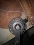
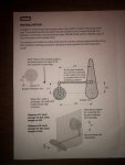
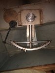
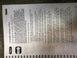
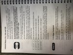
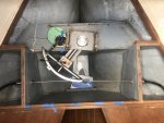
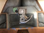
The controller of my Cetrek 730 autopilot is displaying the rudder is 10 degrees to port although it is midship. The autopilot never had any issues other than a fading LCD controller screen. I did drop the Rudder recently and reinstalled it but the Rudder Feedback Unit 930 809 arm was only detached from the quadrant and placed back later. There were no other changes to the quadrant and it was reinstalled and aligned with the rudder and wheel midship exactly as it was. Furthermore, I tested the pilot while on the hard and the controller displayed the rudder position faithfully. However, once back in the water I noticed the display is showing the rudder is 10 degrees to port while it is midship. The installation guide notes the RFU arm must be parallel to the rudder arm when rudder is midship. It is not parallel and i believe it never was, however, it was working always perfectly. Indeed the alignment marks on the RFU are not aligned. I believe they never were. I can't see how this went out of alignment. To realign according to the guide, the threaded rod should probably be shortened. My quadrant setup is a bit weird, it is not midship when the rudder is, and it seems that with my setup I can never achieve what the guide instructions are. I went through the manual's Rudder Settings Routine yet it stated that before begining the display should show no more than -/+ 5 degrees off center and instructs to readjust the RFU center position if it is not, something that will require massive changes to the RFU, rod and arm. Yet the quadrant position, the RFU and its arm or attachment point were never messed with and their positions are as they have always been. I can't get my head around what happened and how to correct it.
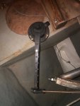
IMG_0471.jpgIMG_0469.jpgIMG_0472.jpgIMG_0470.jpg
 

PaulRainbow

Well-known member
Joined
16 May 2016
Messages
15,969
Location
Suffolk
Visit site
Irrespective of whether you think it worked correctly before, or not, the installation is incorrect. If you adjust the RFU to centre when the rudder is centred, it won't be right at all rudder angles.

As a starting point, you should fit the RFU according to the instructions.
 

vas

Well-known member
Joined
21 Jun 2011
Messages
7,936
Location
Volos-Athens
Visit site
well, a/p shows correctly that rudder is to port from your second pic dots closeup.
Seeing that you're not happy/willing/able to do as Paul says above, I'd at least get the arm dot to align to the middle dot on the rfu housing when straight ahead. Now the fact that it wont be accurate when fully port or stbrd is (imho) a minor issue compared to having the thing not showing correctly straight ahead.

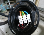
fwiw, it's a plain potentiometer in there with a couple of resistors sealed at the bottom with a round black disk with some glue. When removed to drop the rudder it may somehow managed to gather some dump and values are shifted. Or a cable connector somewhere in the vicinity got damaged/dump. Or something similar with verdigris on the a/p side on connectors.
but for sure would start with aligning the dots

V.
 

tillergirl

Well-known member
Joined
5 Nov 2002
Messages
8,388
Location
West Mersea
Visit site
Agree with Paul. You must have a parallelogram between the tiller arm and the RFU arm, and, if the tiller arm is off centre vis-a-vis the rudder blade you need to have an offset angle in the software setup. I think my system is limited to 10 degrees. Has the cable slipped on the quadrant?
 

CalicoJack

Active member
Joined
5 Jan 2004
Messages
566
Location
Chatham, Kent
Visit site
We have the same system but with rod steering which has two points of adjustment. One is a bottle screw which adjusts both the rudder and consequently the Cetrek unit. Alternatively it is possible to adjust just the Cetrek unit by screwing in/out the treaded rod.
 

yanay

New member
Joined
5 Dec 2019
Messages
24
Visit site
5B727DDD-A7B2-4BAC-A8B1-9660A48D2647.jpegD07DF509-964A-4CC5-84F7-B048016884A0.jpeg5B727DDD-A7B2-4BAC-A8B1-9660A48D2647.jpegD07DF509-964A-4CC5-84F7-B048016884A0.jpegreinstalled the RFU to be always parallel to the quadrant arm and dots are aligned when rudder is centered but the controller now displays 5 degrees to port when rudder is centered. Went through doc side settings and sea trial settings. Entered the rudder center point manually as well as rudder mechanical limits, into the settings. Now when running doc side rudder settings and entering center, starboard, rudder angle, port, to starboard, ENTER, the system should be moving the rudder 4 times end to end, but it goes to starboard end, crosses the center and stops at 15 degrees on port, as if it reached the limit. Going through the manual I can’t see where it’s going wrong.
anyone experienced such issue with D8A6B02E-737C-4308-A1A3-C9EB6B2BE8F3.jpeg39B0DA58-6BA4-4E2E-8F01-B6E7616E5F9C.jpeg6A0C983E-A913-4334-B912-BE97923E54F0.jpegcetrek rudder settings?
 

tillergirl

Well-known member
Joined
5 Nov 2002
Messages
8,388
Location
West Mersea
Visit site
That sort of incomplete action was similar to the failure of my previous system but it was a quite different system and era. Are the rudder limits set at 15 degrees?
 

yanay

New member
Joined
5 Dec 2019
Messages
24
Visit site
That sort of incomplete action was similar to the failure of my previous system but it was a quite different system and era. Are the rudder limits set at 15 degrees?
I can set it manually and tried 30, 35, 40 (quadrant arm degrees was measured and it actually 35&40 from center when on hard starboard and port respectively). These manual changes only made it not complete the whole movement range on the first center to hard starboard and it always stopped on the way to the port hard over, 15 degrees past center and way before the actual limit.
 

vas

Well-known member
Joined
21 Jun 2011
Messages
7,936
Location
Volos-Athens
Visit site
now that I'm reading this again, I think you're better off buying a VDO white knock off RFU from CN for 10-15quid and trying it on.
IIRC (been 7+years though) original cetrek item "flatspotted" and reading the values with a decent multimeter resistance wasn't smooth as you were moving the lever. Was trying to use it to implement an analogue to NMEA2000 rudder feedback sensor with the old CETREK item on a Garmin A/P. Eventually used the 10quid CN and it's working fine for all these years.
considering it's a simple cheap potentiometer in there, it's hardly surprising.

V.
 

yanay

New member
Joined
5 Dec 2019
Messages
24
Visit site
now that I'm reading this again, I think you're better off buying a VDO white knock off RFU from CN for 10-15quid and trying it on.
IIRC (been 7+years though) original cetrek item "flatspotted" and reading the values with a decent multimeter resistance wasn't smooth as you were moving the lever. Was trying to use it to implement an analogue to NMEA2000 rudder feedback sensor with the old CETREK item on a Garmin A/P. Eventually used the 10quid CN and it's working fine for all these years.
considering it's a simple cheap potentiometer in there, it's hardly surprising.

V.
It’s possible the RFU is faulty, however when moving the wheel it does display full range of movement on the screen so this may indicate the sensor is working. But when going through the calibration settings it stops after the first hardover and indicates it’s at 15 degrees.
 

tillergirl

Well-known member
Joined
5 Nov 2002
Messages
8,388
Location
West Mersea
Visit site
I would think the RFU is just a potentiometer as vas says. Can you get access to the plug from the RFU? Getting a multimeter across the wiring should indicate if the pot is working OK.


If you get consistent readings, the problem would lie within the Instrument Head I think.
 

vas

Well-known member
Joined
21 Jun 2011
Messages
7,936
Location
Volos-Athens
Visit site
I would think the RFU is just a potentiometer as vas says. Can you get access to the plug from the RFU? Getting a multimeter across the wiring should indicate if the pot is working OK.


If you get consistent readings, the problem would lie within the Instrument Head I think.
+1

actually I've taken the thing apart, it IS an el cleapo pot! I've got pics to prove it, but I'm not going to search 5k pics out of the four year rebuilt to find the right one ?
 

yanay

New member
Joined
5 Dec 2019
Messages
24
Visit site
+1

actually I've taken the thing apart, it IS an el cleapo pot! I've got pics to prove it, but I'm not going to search 5k pics out of the four year rebuilt to find the right one ?
It gives resistance readings at the CPU end, as the RFU arm is moved. Not sure which numbers I am looking for at which angle. I am reluctant to open the thing up and possibky damage it. I removed the black arm , there's a center shaft and a plastic nut on it. How do you open it?
 

vas

Well-known member
Joined
21 Jun 2011
Messages
7,936
Location
Volos-Athens
Visit site
you are lucky, only took me 5mins to find it...
unbolt, turn around, prise the round plastic bit slightly in recess with a thin screwdriver/blade. Just a few drops of glue (by now dried out!) holding it in place.
As I said at the beginning of the thread, make sure no dampness in there. Other than that, don't think you can do much about it other than replace.
Just check on the cable CPU end if the values are smoothly changing! Mine weren't and once it jumps to something silly I feel that the CPU craps out and locks to something unrelated to (what by then proper value) the RFU is reporting.
Carefully move the arm from end to end (of expected movement!) and note down the values. Then move it a bit more abruptly and see if at any point it went off bounds. Judge from there.

1674628029626.png

being electrics and a longish run from RFU to CPU, I'd also add temporarily a cable replacing the existing wire it up instead and check behaviour, maybe the cable and not the RFU after all. CPU connectors are v.fancy, not really prone to vertigris, but undo and clamp again just in case (ALL OF THEM!)

V.
 
Top