goeasy123
Well-Known Member
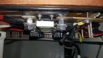
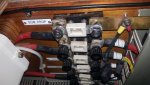
I have a 4.4KW Sidepower SE80 bowthruster. The battery end of the cable is fused with a 426A ANL fuse that comes with the fitting kit. The fuse gets so hot it's melting the plastic of the fuse holder. What's wrong. How do I fix it?

")