Beneteau Switch Panel

Ivor Schull

New Member
Joined
21 Oct 2013
Messages
1
Visit site
Hi,

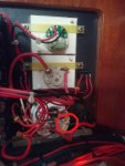
On my 2004 Beneteau there are 16 red led indicator lights on the switch panel that have stopped working. On the earth return there is, what looks like a resistor, which is plain brown with the letters VF on it. Could anyone please tell me what this is so that I can replace it because when I cross the resistor with wire the lights work. Any help would be much appreciated.
Thanks,
Ivor
 
Last edited:
Reviving this old thread as I have the same problem on the DC switch panel on my Beneteau 473.

All the switch indicator lamps are out.

The positive (anode) wire from each LED is connected to the load side of the appropriate switch. The negative (cathode) wires from each LED are soldered to the back of a small circuit board (on the front of which are mounted the switch label backlights).

All the negatives on this board appear to be common and connect to a black wire. Following the negative return wire, it is then connected to the panels common negative return (which is also the return for the voltmeter and the panels 12 volt cigarette lighter type socket.

Before the negative from the LED’s connects to the common negative return is what looks like a small resistor, and there is no continuity across this “resistor”. I cannot see any colour code bands on this component, and according to the OP, the only markings on it are the letters VF, (and no amount of goggling has provided any clues)

I cannot see any other components soldered to the circuit board, only the back lights themselves.

What puzzles me is that the switch indicator LED’s are wired in parallel, and I cannot see any individual resistors connected to each LED. From what I have found out from google, LED’s in parallel on a 12V circuit should each have their own resistor (in a series circuit one resistor can be used for all the LED’s)
Is it possible that a resistor is fitted inside each LED housing?

I have attached picture of the panel, and link to similar looking LED (same dimensions as the ones fitted in the panel)

https://media.digikey.com/photos/Lumex Photos/SSI-LXH312ID-150.jpg

I’m hoping that some electrical guru on the forum could possibly explain what the component is, is it a resistor, or something else?

I have asked Beneteau for information, but I’m not holding my breath.
 

Attachments

At a guess Vf would be forward voltage. Assuming your LED spec sheet is for the LEDs in the system they are 2V and want 30mA current. This leaves the resistor with around 10V so if my amateur guessing is right that's 333 Ohm resistor, 332 or 340 are the closest standard values. I may well be wrong.

Regarding the parallel thing you'd want to trace out the circuit. It's possible that they just didn't care enough and the LEDs will get dimmer/brighter depending how many are on. As long as they don't blow a component then probably all good. Considering that the resistors seem to be blowing, it would suggest the design is bad! If it was a 1 Watt resistor then it's entirely feasible that turning on all the LEDs could have blown it.
 
Hi,
Its been fine for 20 years. In the past, all the LED indicators have remained at the same level of brightness with one on, or all 16 on.
Thinking about it, I wonder if the LED housing contains a resistor, and the resistor in the return line is in fact for the backlights. The backlights are controlled by one switch, so the backlight LED's could be connected in series.
Hopefully I'm on the boat this weekend, and will measure the resistance across the terminals of the individual switch LED's.

Cheers
Nigel
 
Did you find the resistors? Quite curious where they are now :ROFLMAO:

Me too.

Hoping the fuses will arrive today from Farnells. I'm up to the boat tomorrow.
Want to measure the resistance across the existing LED's and compare it to the replacement LED's I have ready to go in.
Once all thats done, will check what the voltage is across the LED terminals
 
Did you find the resistors? Quite curious where they are now :ROFLMAO:

I doubt there are any visible, most likely "built in" to the LED package. I have some pretty small LEDS, my compass ones are "grain of rice" LEDS. Just been re-wiring a switch panel on a customers boat and the LEDS on the "mimic" panel are tiny. None of them have separate resistors.
 
I'm guessing if I measure the resistance across the excisting LED's and compare that to a standard red 3mm LED, I should get the answer.
Beneteau want approx £10 per LED, plus import tax and postage. A 3mm red panel mount LED costs about 80p, and I could use these with an appropriate sized resistor soldered to one of the tails.

I'd just measure the voltage at the LED connections, if it's 12V the LEDS have pre-wired resistors, which i'd suspect to be the case. You can buy 12V 3mm LEDS (pre-wired) for pence. A quick look on Ebay turned these up, £3.49 for 10 inc post:

3MM Pre-Wired LED Ultra Bright Water Clear Bulb 9V ~ 12V Prewired LED | eBay
 
New fuse soldered in. Checked the voltage at the working indicator's and it same as battery voltage, so I'm guessing they are pre-wired with a resistor.
The ones Paul linked to would work, but I got some panel mounted LED's with the same housing as the originals, and soldered a 820 ohm reisistor on the anode side and it works perfectly.

Had a bit of a google, and came across these, look pretty much same as original.
LED Panel Mount Indicator Red .157" 12V Wire Leads - VCC
 
Last edited:
Top