Backbone query

dgadee

Well-known member
Joined
13 Oct 2010
Messages
3,913
Visit site
Rewiring and sorting out backbone. What I have is 12v going in one end and one terrminator (can't see a second one) with cables off at junctions. What I want to know, is there some way I can add two nmea2000 devices to one drop cable (or whatever it is called)?

Can I take from middle of backbone or could I add to where terminator is now and put terminator at the furthest end?
 

Attachments

  • IMG_20240711_142200927_1.jpg
    IMG_20240711_142200927_1.jpg
    633.5 KB · Views: 17

Hoolie

Well-known member
Joined
3 Mar 2005
Messages
8,146
Location
Hants/Lozère
Visit site
I think you will have to tee off the backbone as shared connections are non-compliant. Your 12v feed on the end is also non-compliant and should be fed through a dedicated power drop cable, ideally near the middle of the backbone. Both ends should have a terminator.
 

dgadee

Well-known member
Joined
13 Oct 2010
Messages
3,913
Visit site
I think you will have to tee off the backbone as shared connections are non-compliant. Your 12v feed on the end is also non-compliant and should be fed through a dedicated power drop cable, ideally near the middle of the backbone. Both ends should have a terminator.
That is what I thought. Probably easier to have two sections of tee's anyway - one up at the chart table and one down where the depth, autopilot, etc. arrive. I presume you can have 3m of cable between the two sections of tee's?
 

Sandy

Well-known member
Joined
31 Aug 2011
Messages
21,776
Location
On the Celtic Fringe
duckduckgo.com
Rewiring and sorting out backbone. What I have is 12v going in one end and one terrminator (can't see a second one) with cables off at junctions. What I want to know, is there some way I can add two nmea2000 devices to one drop cable (or whatever it is called)?

Can I take from middle of backbone or could I add to where terminator is now and put terminator at the furthest end?
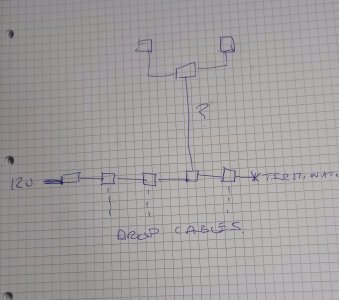
I've read that it is best practice for the power to be somewhere in the middle of your backbone, but suspect this is for long runs - you will need terminators at either end

I run four things, Garmin wind and water displays, air temp and barometer sensors, above the hatch from one drop cable. Works for me.
 

PaulRainbow

Well-known member
Joined
16 May 2016
Messages
17,048
Location
Suffolk
Visit site
That is what I thought. Probably easier to have two sections of tee's anyway - one up at the chart table and one down where the depth, autopilot, etc. arrive. I presume you can have 3m of cable between the two sections of tee's?
Yes, you can. But you need to move the power cable from the end, to a tee and fit the other terminator in its place.

You can add tees anywhere along the backbone, but the ends must both be terminated.
 

dgadee

Well-known member
Joined
13 Oct 2010
Messages
3,913
Visit site
Yes, you can. But you need to move the power cable from the end, to a tee and fit the other terminator in its place.

You can add tees anywhere along the backbone, but the ends must both be terminated.
Is the cable for the backbone different from the drop cable? Or are they interchangeable?

When you say 'must' do you mean 'must' or 'should'?
 

wonkywinch

Well-known member
Joined
30 Jul 2018
Messages
2,026
Location
Hamble, UK
Visit site
The wind indicator in my B&G kit has a terminator built in. The other one, a specific device, is plugged into the other end if the backbone near a chart plotter at the helm so it initially appeared I only had one terminator in the system.

Each terminator is a 120 ohm resistor so with power disconnected, the 12v supply pair should show 60 ohms resistance with 2x 120R in parallel.
 

dgadee

Well-known member
Joined
13 Oct 2010
Messages
3,913
Visit site
The wind indicator in my B&G kit has a terminator built in. The other one, a specific device, is plugged into the other end if the backbone near a chart plotter at the helm so it initially appeared I only had one terminator in the system.
Interesting. It is a B&G wind thing on my new to me boat. (The direction works but the spinners don't spin.) But it is taken off a tee, not the end of the backbone.
 

pmagowan

Well-known member
Joined
7 Sep 2009
Messages
11,838
Location
Northern Ireland
sites.google.com
I suspect ‘should’! My understanding is that a drop cable is essentially just a mini junction box splitting the wires in two so really there is no difference between the drop cable and the backbone. I suspect most of this is about standardisation rather than any electrical laws! Could be wrong though and generally best to keep to spec even if only for sanity sake when trying to problem solve later
 

Martin_J

Well-known member
Joined
19 Apr 2006
Messages
4,403
Location
Portsmouth, UK
Visit site
Each terminator is a 120 ohm resistor so with power disconnected, the 12v supply pair should show 60 ohms resistance with 2x 120R in parallel.

Think you've had a senior moment... With the correct number of terminators (two) in place the resistance can be measured as 60 ohm between the blue and white data wires.

Do this measurement with the power to the bus/backbone turned off.

If your measurement is about 120 ohm across blue and white, then you've got just one terminator connected and will need to add a second.

If the resistance measured between blue and white is 40 ohm or less then you've got three or more terminators connected.

The most I've found on one bus/backbone was five terminators!

In most small networks you will get away with adding a couple of devices onto one drop cable... That can actually happen when you daisychain a couple of Raymarine displays for example.
 

Martin_J

Well-known member
Joined
19 Apr 2006
Messages
4,403
Location
Portsmouth, UK
Visit site
As others have said... some masthead wind transducers rely on the backbone going right to the masthead. This is because it would be too long for a drop cable to reach the top of most masts. The manufacturer then adds a terminator internally within the masthead wind unit. Not strictly compliant because terminators must be external (but it works and saves an extra connection out in the open).

You can't even say a particular manufacturer does it the same for each masthead unit in their range so you need to be aware as to whether you have NMEA 2000 backbone to the masthead, or whether you have the NMEA wind electronics at the foot of the mast with a manufacturer specific (but not NMEA 2000) cable to the the masthead.
 

WindyWindyWindy

Active member
Joined
5 Feb 2022
Messages
406
Visit site
The backbone - the data wires - should show very close to 60ohms on a multimeter with no power on. When the power is on that will change.
The power supply, if it's a significant supply, should be fairly central, but lots of larger devices have separate power.
There's a unit count for each device that expresses power consumption of the device and that should be roughly balanced if it's a big network.

A very long drop cable will have its own resonance which is what the resistors are supposed to attenuate, it will work a bit, but a very long drop cable is best treated as a backbone. They are the same thing really. The terminators should be as far from each other as possible on the network. There should only be two.

Essential viewing...
 

WindyWindyWindy

Active member
Joined
5 Feb 2022
Messages
406
Visit site
The manufacturer then adds a terminator internally within the masthead wind unit. Not strictly compliant because terminators must be external (but it works and saves an extra connection out in the open).
It might work, but if there are also two other 120ohm terminators in the network then you're down to 40ohms which isn't enough. The solution will probably involve either a higher resistance termination at the mast head, or removing a termination further down.

If you imagine a double T topology where you have a normal back bone and a drop with two devices. If the drop has two terminators and the backbone has two terminators then the total resistance will be a lot lower than the 60 ohm target..

The caveat is that electromagnetic resonance is not simple hence the simplified drop cable bus topology, but if you've got 60ohms total you should be ok..
Also this:
 

PaulRainbow

Well-known member
Joined
16 May 2016
Messages
17,048
Location
Suffolk
Visit site
It might work, but if there are also two other 120ohm terminators in the network then you're down to 40ohms which isn't enough. The solution will probably involve either a higher resistance termination at the mast head, or removing a termination further down.

If you imagine a double T topology where you have a normal back bone and a drop with two devices. If the drop has two terminators and the backbone has two terminators then the total resistance will be a lot lower than the 60 ohm target..

The caveat is that electromagnetic resonance is not simple hence the simplified drop cable bus topology, but if you've got 60ohms total you should be ok..
Also this:
It does work, because the masthead unit is plugged into one end of the backbone, therefore the cable going up the mast is backbone, terminated at the masthead unit.
 

Martin_J

Well-known member
Joined
19 Apr 2006
Messages
4,403
Location
Portsmouth, UK
Visit site
By 'internal terminator within the masthead unit not being compliant'.. better wording would have been that this would mean the MHU could no longer be sold by the manufacturer as being an NMEA2000 compliant device..

Similar reason for the small displays that are daisy-chainable not being certified as compliant. Useful if you only have one drop cable to where you want to install a couple of instruments displays.. but the instruments themselves would not have been certified as compliant.
 

PaulRainbow

Well-known member
Joined
16 May 2016
Messages
17,048
Location
Suffolk
Visit site
The backbone - the data wires - should show very close to 60ohms on a multimeter with no power on. When the power is on that will change.
The power supply, if it's a significant supply, should be fairly central, but lots of larger devices have separate power.
There's a unit count for each device that expresses power consumption of the device and that should be roughly balanced if it's a big network.

A very long drop cable will have its own resonance which is what the resistors are supposed to attenuate, it will work a bit, but a very long drop cable is best treated as a backbone.

Drop cables should be no more than 6m. If you need to go farther than that, run a backbone cable, stick a tee on the end, then terminate the tee. You cannot treat a drop cable as a backbone cable, it's one or the other.
They are the same thing really. The terminators should be as far from each other as possible on the network. There should only be two.
As far from each other as possible ?? They should be at opposing ends of the network, i think that's as far as possible. ;)
 

dgadee

Well-known member
Joined
13 Oct 2010
Messages
3,913
Visit site
Looking on to the cable connector for the B&G wind vane, which two lines do I put the multimeter on to determine if it has a built in terminator?
 

Martin_J

Well-known member
Joined
19 Apr 2006
Messages
4,403
Location
Portsmouth, UK
Visit site
You need to determine first of all if you have NMEA2000 to the mashead or if there is a 'box of electronics' at the bottom that connects to the NMEA2000 (in which case NMEA2000 does not then go to the masthead) before you try measuring at that point.

To check if the correct number of terminators are on your backbone, assuming you do have just one backbone, power off the backbone and measure across the data wires (white and blue).

Easiest to do if you have a spare spur cable that you can plug into any T piece (and that has bare wires at the multimeter end). Just cut a short spare cable in half for this.

You should get the same measurement of [very close to] 60 ohms when plugged into any T piece on the backbone (which will show that you have the correct/two terminators).
 

Martin_J

Well-known member
Joined
19 Apr 2006
Messages
4,403
Location
Portsmouth, UK
Visit site
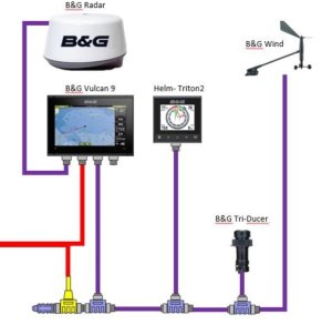
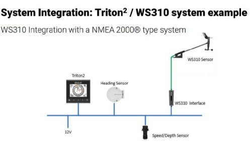
Maybe these two diagrams show the different styles of MHU (MastHead Unit) connectivity more clearly..

In this first diagram the backbone is the lower horizontal purple line. It has a terminator on the left hand end and extends all the way up to the masthead. The wind MHU designed for this connection will have a built in terminator.

Screenshot_20240712-090501_Samsung Internet.jpg


In this next diagram, the NMEA2000 wiring is blue. The WS310 interface actually just looks like a bulky plug. It has all the NMEA2000 transceiver electronics within it. The green wires going up the mast are not NMEA2000 at all.

The blue backbone will therefore require a terminator at each end.

20240712_090554.jpg
 
Top