Are busbars necessary for this set up?

steve yates

Well-Known Member
Joined
16 Oct 2014
Messages
4,105
Location
Benfleet, Essex/Keswick, Cumbria
Visit site
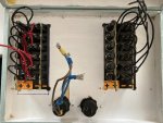
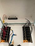
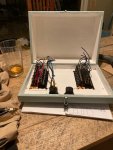
The pic is of my fuse box, I basically have enough fused switches for everything on board the small boat to have its own dedicated switch, even down to compass light!

Given that, can I wire all the various feeds directly into the switches without using seperate busbars?

And after asking that, it occurs to me that I will need lots of loop of wires to allow the box door to drop down open, so perhaps a matching busbar for each switchpanel fixed to the inside of the box with a long enough cable then continuing each feed to the relevant switch could be a lot tidier and more manageable?

I think I may have answered my own question but I would still like to know if separate busbars are actually required here or just convenient?
 

Attachments

  • bethfran-fusebox-2.jpg
    bethfran-fusebox-2.jpg
    110.9 KB · Views: 83
Last edited:
Oops, sorry, I did indeed. Now added!
If you find you are trying to fit more than ( 3 at the most) wires on the same terminal you need to use a busbar

You will probably need busbars for all the negative connections and perhaps for a common positive connection unless you daisy chain the positive connections.

You will probably need terminal blocks for the connections between the fixed wiring and the "loop wires"
 
Last edited:
Best practice would be a positive and negative bus bar with individual wires to each fuse/switch. Same for the negatives. The primary wire that feeds the bus bar needs to be suitably sized for all the loads - this may include peak loads of any motors. This should also be upsized to allow for any future expansion.
I am not a fan of "daisy-chaining" the wires up the fuses/switches. If one wire or connection fails at the beginning you will lose everything after that.
Definitely over-engineer this stuff, it rarely fails at a good time.
 
Given that, can I wire all the various feeds directly into the switches without using seperate busbars?

I think you might get more answers if you described a bit more what is seen in that picture.
Are there also negatives in the box or only positives? When you mention feeds, do you mean the cables from the battery? Or the wires feeding various equipment? And do you actually mean busbars or rather terminal blocks, like these?
Terminal Block - Blue Sea Systems
 
Its a matching pair of fused switch panels
I think you might get more answers if you described a bit more what is seen in that picture.
Are there also negatives in the box or only positives? When you mention feeds, do you mean the cables from the battery? Or the wires feeding various equipment? And do you actually mean busbars or rather terminal blocks, like these?
Terminal Block - Blue Sea Systems
ok, i have attached some more pics to clarify. I might have sone if terminology wrong? but i definitely meant busbars not terminal blocks. There are two fused panel switches , i can connect battery feed directly to the pos bar on them but it looks quite flimsy. I am thinking it will be better to use a couple of pos and neg bars like the one in the back of the box to keep the cabling under control. By feeds I mean the wires from the loads, but really i am asking about both I suppose.
I ‘m looking to make the cabling into and out of this box as practical, neat and controllable as possible.
One thing im not sure about is how , after getting pos feed from battery to one switch, how i get it to the other.
I presume i would use a pos bus, battery cable to bus and two cables from bus , one to each switch panel?
6172B92F-658C-4C33-B3F5-96811753F5EF.jpeg
 

Attachments

  • A16369AD-516B-4D78-9F36-359DEBCC566A.jpeg
    A16369AD-516B-4D78-9F36-359DEBCC566A.jpeg
    117.9 KB · Views: 30
  • B5624728-8029-46B9-8F86-E8888ADA8735.jpeg
    B5624728-8029-46B9-8F86-E8888ADA8735.jpeg
    62.1 KB · Views: 32
  • D196517B-6DE8-4CF9-BC2B-4148AB880577.jpeg
    D196517B-6DE8-4CF9-BC2B-4148AB880577.jpeg
    92.3 KB · Views: 30
I ‘m looking to make the cabling into and out of this box as practical, neat and controllable as possible.
One thing im not sure about is how , after getting pos feed from battery to one switch, how i get it to the other.
I presume i would use a pos bus, battery cable to bus and two cables from bus , one to each switch panel?
These photos were much better, but have to say I find those positive and negative markings (++ and --) a bit confusing...
There appears to be a brass (?) bar already soldered to the fuse holders (positive) and another bar soldered to the rocker switches (negative, presumably for the illumination of these).
I think you should connect the positive feed from the battery at the positive bar(s) only.
The positive feeds to the individual loads would connect to the terminals on the rocker switches which now carry pig tails (these could be removed, as per instructions).
On the negative side you would need some convenient way to connect the individual feeds to the loads. It doesn't appear as if there was a means of doing so on the negative soldered bars? A couple of the bus bars as pictured in the second photo would be OK, I guess. These could be attached in the area between the two panels. I would put a cover (acrylic?) over these, so that a loose positive wire could not easily touch.
For the same reason I would put for instance a split hose over the negative brass bars of the panels.
 
Top