mogmog2
Well-Known Member
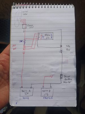
I'm having trouble with this cheapo PZEM -031 multi meter I bought to get an idea of the output from my wind generator (at the moment I have only a Nasa BM2 which gives a net reading and includes solar)
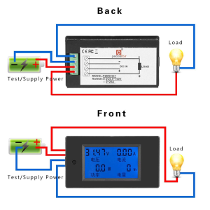
AIUI, the load should be pos from the turbine charge controller and neg to the house battery (bus bar) and the two DC are just 12v (from the house bus bars) to power the unit?
However, if I wire it thus, the DC negative sparks when the wire touches the terminal and gets warm if left in contact.
Any ideas? Many thanks

 then work, or not as the case may be. What make Geny. and controller?
