Alternator Voltage / Replacement

Ammonite

Well-Known Member
Joined
7 Feb 2007
Messages
1,180
Visit site
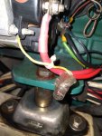
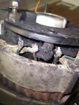
Today I discovered that my 60A alternator on my MD2040 is putting out around 15.5v at 1500rpm although the voltage at the starter and house batteries (12v SLAs) is around 14.7/8v which I think (?) is the result of having a diode splitter between the alternator and batteries. My initial thoughts were that the regulator is faulty but having removed the cover on the alternator the negative side looks to have got very hot and the plastic / components (diodes?) have melted Any ideas what might have caused this?
By way of background this is my first season with the boat and I recently discovered that the previous owner had the battery charger set to AGM (14.8v) rather than SLA. The starter and house batteries were also replaced just before I bought her as all three were cooked / stinking of sulphur. The mains charger had been connected for several months while on the hard.
My plan is to replace the alternator with one from partsforengines but I don't want to do this if the same thing is going to happen again. There are no other obvious electrical faults. Thanks

Edit: the old solar regulator may have contributed to the previous batteries demise as the connections quite literally fell apart due to corrosion. It now has a nice new victron smart controller
 

Attachments

  • 20210911_164747_compress78.jpg
    20210911_164747_compress78.jpg
    357.7 KB · Views: 42
Last edited:
Is there any sort of external regulator (Balmar etc) ?

Is the alternator machine sensed or battery sensed ? Could be either on your engine and battery sensing could explain the difference, as you say, with the diode splitter. You could try disconnecting the alternator wire from the diode and connect it to the engine battery terminal of the diode, the voltage should then be very similar at the alternator and the battery (obviously only check at the engine battery).
Thanks Paul. There's no external regulator and it's a Valeo A13N234 fitted to a MD2040C. The (internal) regulator is a Cargo 136910 / VR-PR7736. The alternator charges the three banks (there's also a thruster battery in the bow) via the splitter and with the battery switch on "both" (I know you hate these!) I was seeing 15.4/5v at the alternator and 14.8v at the house and starter batteries. When I switch the battery switch to the house bank I get 14.7v at the house and circa 15.1v at the starter. Presumably this is due to a combination of the loss via the splitter and the load moving solely to the house bank? I added the photo just after you posted and you can see its well and truly fried! I have a Nasa battery monitor (house and starter voltage) and this reads exactly the same as my multimeter.
 
Reading up on this I hoping it's as simple as the regulator failing and the increased voltage causing the rectifier diodes to run hot / melt the surrounding plastic in which case the replacement alternator should it but I'd in interested to hear from those in the know
 
Lack of ventilation and possibly bad connections would be the cause. Alternators are designed to run hot, to a degree.

Check that the fan is the correct hand, it should pull cooling air into the rear of the casing.

Running on flat batteries at low engine speeds heats alternators more than thrashing them at high revs so charging at tickover is bad.
 
Silicon diodes drop 0.7volts along their length. Thus 15.5 at alternator should give 14.8 at battery. Then about 14.4 is what you want at battery under charge, leaving maybe 12.7 when not under charge. So both alternator and diode seem fine from that, and battery may be fading but its clearly not short circuited.

Is there some charging issue that causes you a worry or is it just the evidence of past excess heating at the diode block?
Sorry, i'm not sure I follow your logic. From what I've been able to ascertain a valeo A13N234 alternator is designed to output a constant 14.5v so with the battery splitter and any cable loses I'd expect marginally less than this at the batteries once they are fully charged. I haven't had a chance to implement Paul's suggestion but if I bypass the battery splitter I'm pretty sure I'm going to see 15v+ at the starter battery i.e. pretty much the same as alternator is outputting confirming that the alternatoris duff. Also, even if I had a battery sensing alternator isn't this is used to compensate for any loses between the alternator and the battery and to ensure 14.4v is delivered to the battery, whereas I'm seeing over 15v when being charged via the battery splitter but not underload and 14.8v with the load restored. On my old Beta 20, for example, I never saw more than 14.4v at either bank and I was under the impression the setup was similar although I didn't have a battery splitter before.
Just to be clear the battery splitter appears fine and it's the negative side of the rectifier plate that has melted.

Edit: My battery splitter is the low voltage loss type, similar to a Victron Argofet. Apologies - I referred to it as a diode splitter before so the losses between alternator and battery should be minimal
 
Last edited:
Having looked into this a little more I've noted that the B+ terminal from the alternator regulator is connected to the starter motor solenoid rather than the B+ terminal on the alternator. See photo. I'm assuming this means it's battery sensed? I'm also guessing there may be a diode somewhere on the sense wire designed to raise the charging voltage to 14.8v which is why when the battery switch is on 2 (house) I'm seeing 14.8v at the house batteries but over 15v at the starter battery, but when on Both I'm seeing 14.8v on both banks? The see through connector on the yellow regulator wire isn't a cunningly designed diode is it? I was under the impression it was just joining the two wires.

I'm also wondering if the boat had AGMs rather than SLAs at some point which would explain why the alternator voltage has been changed, along with the mains charger profile (and why the last lot of SLAs were cooked) so maybe the alternator is working as it should despite the heat damage on the rectifier?
 

Attachments

  • 20210911_125531_compress84.jpg
    20210911_125531_compress84.jpg
    394.4 KB · Views: 24
Last edited:
Silicon diodes drop 0.7volts along their length. Thus 15.5 at alternator should give 14.8 at battery. Then about 14.4 is what you want at battery under charge, leaving maybe 12.7 when not under charge. So both alternator and diode seem fine from that, and battery may be fading but its clearly not short circuited.

Is there some charging issue that causes you a worry or is it just the evidence of past excess heating at the diode block?
"have got very hot and the plastic / components (diodes?) have melted"
 
Having looked into this a little more I've noted that the B+ terminal from the alternator regulator is connected to the starter motor solenoid rather than the B+ terminal on the alternator. See photo. I'm assuming this means it's battery sensed? I'm also guessing there may be a diode somewhere on the sense wire designed to raise the charging voltage to 14.8v which is why when the battery switch is on 2 (house) I'm seeing 14.8v at the house batteries but over 15v at the starter battery, but when on Both I'm seeing 14.8v on both banks? The see through connector on the yellow regulator wire isn't a cunningly designed diode is it? I was under the impression it was just joining the two wires.

I'm also wondering if the boat had AGMs rather than SLAs at some point which would explain why the alternator voltage has been changed, along with the mains charger profile (and why the last lot of SLAs were cooked) so maybe the alternator is working as it should despite the heat damage on the rectifier?

The B+ terminal on the alternator and the positive terminal on the starter solenoid are meant to be connected, so it shouldn't matter where the regulator is connected. Logically though it's easier to connect the regulator to the alternator.

Without knowing how your 1-2-Both switch and alternator output are wired, it's impossible to say why the engine battery is sometimes getting a higher voltage.

The see-through connector is just that, a connector.

Presumably you're getting a new alternator, or having yours repaired. Whichever, why not install it with wiring according to the MD2040 wiring diagram? And, before doing that, sort out whether or not there's a battery sensing wire.

Incidentally, the yellow wire on the regulator is usually the D+ connection.
 
Having looked into this a little more I've noted that the B+ terminal from the alternator regulator is connected to the starter motor solenoid rather than the B+ terminal on the alternator. See photo. I'm assuming this means it's battery sensed? I'm also guessing there may be a diode somewhere on the sense wire designed to raise the charging voltage to 14.8v which is why when the battery switch is on 2 (house) I'm seeing 14.8v at the house batteries but over 15v at the starter battery, but when on Both I'm seeing 14.8v on both banks? The see through connector on the yellow regulator wire isn't a cunningly designed diode is it? I was under the impression it was just joining the two wires.

I'm also wondering if the boat had AGMs rather than SLAs at some point which would explain why the alternator voltage has been changed, along with the mains charger profile (and why the last lot of SLAs were cooked) so maybe the alternator is working as it should despite the heat damage on the rectifier?
I may be mistaken but that yellow wire seems to terminate in that connector. Is it just possible that the sensing has been disconnected and the alt. is producing max voltage continually?
 
The B+ terminal on the alternator and the positive terminal on the starter solenoid are meant to be connected, so it shouldn't matter where the regulator is connected. Logically though it's easier to connect the regulator to the alternator.

Without knowing how your 1-2-Both switch and alternator output are wired, it's impossible to say why the engine battery is sometimes getting a higher voltage.

The see-through connector is just that, a connector.

Presumably you're getting a new alternator, or having yours repaired. Whichever, why not install it with wiring according to the MD2040 wiring diagram? And, before doing that, sort out whether or not there's a battery sensing wire.

Incidentally, the yellow wire on the regulator is usually the D+ connection.
Thanks. I will have a look at the original wiring diagram but as with a lot of 20 year old boats it's been modified over the years and didn't originally have a low loss splitter. I'm also led to believe it had seperate isolators for the starter and house banks and a heavy duty relay thinking the two banks but now has a 1-2-Both switch.
Incidentally did you mean D+ because all the diagrams I can find of the cargo 136910 regulator show this as B+. On mine the B+ on the alternator goes to the input terminal on the low loss splitter and its only the yellow B+ lead from the regulator that connects to the starter solenoid
 
Take the alternator into a repair shop and get it tested
Just Alternators and Starter Motors Ltd
Alternator supplier · Southampton
Their website mentions alternator repair

Course-Beacham
Vehicle Repair · Southampton
Their website mentions alternator repair
I've used JASM before, if hes still operating he's very good. Out in the wilds near Botley
 
I may be mistaken but that yellow wire seems to terminate in that connector. Is it just possible that the sensing has been disconnected and the alt. is producing max voltage continually?
The yellow wire is joined to another wire in the clear connector and this is connected to the starter solenoid, presumably so it can see the voltage of each battery depending on the position of the 1-2-Both switch
 
I've used JASM before, if hes still operating he's very good. Out in the wilds near Botley
Yes - I've spoken to him. How should I say - he's quite a character!
I may still get it repaired but given I want to use the boat ASAP and it will cost around £100 to have the rectifier and regulator replaced, tested etc I've ordered what is supposed to be a direct replacement from partsforengines which arrives tomorrow. Its a 70amp Prestolite
 
Incidentally did you mean D+ because all the diagrams I can find of the cargo 136910 regulator show this as B+.

No, I intended to write D+. Most of the regulators for your alternator have the yellow wire as the D+ connection (also called "trio"). Your regulator may not adhere to this colour code. It's possible that your boat's electrics have been messed about by people in the past who didn't know what they were doing.

Prestolite alternators are good quality. Be sure that you follow the wiring instructions!
Thanks. The trio is brown on my regulator but the fact that it's an hc-cargo part fitted to a valeo alternator means its already been tinkered with. I'm going to investigate more fully (and follow the prestolite instructions) when the new alternator turns up tomorrow!
 
The B+ terminal on the alternator and the positive terminal on the starter solenoid are meant to be connected, so it shouldn't matter where the regulator is connected. Logically though it's easier to connect the regulator to the alternator.

Without knowing how your 1-2-Both switch and alternator output are wired, it's impossible to say why the engine battery is sometimes getting a higher voltage.

The see-through connector is just that, a connector.

Presumably you're getting a new alternator, or having yours repaired. Whichever, why not install it with wiring according to the MD2040 wiring diagram? And, before doing that, sort out whether or not there's a battery sensing wire.

Incidentally, the yellow wire on the regulator is usually the D+ connection.
With hindsight I don't think the MD2040 wiring diagram is going to help as my setup has clearly been modified. There's no connection from the alternator B+ terminal to the starter motor. Instead the B+ terminal goes to the low loss splitter and in turn to each battery bank. The B+ wire on the regulator also doesn't go to the B+ on the alternator. Instead this is connected to the starter motor in order that it can sense the relevant battery voltage depending on whether 1-2 or Both is selected which means that when running off the house bank only there's a risk of over charging the starter battery as this isn't being sensed, at least thats what I think is happening! Mind you this still doesn't explain why the sensed batteries (depending on the position of the 1-2-Both switch) are being charged at 14.8v rather than 14.4/5v. I'm hoping the latter should be resolved by the new alternator (if not there must be a diode in the sense wire somewhere to boost the charging voltage) and that I should probably connect the regulator B+ to the Alternator B+ (rather than the starter motor) to avoid over charging the unsensed battery????

Also, is it normal for an alternator to be modified as my has so that the regulator is connected to the battery rather than the alternator output thereby turning it into battery sensed rather machine sensed?
 
Last edited:
Also, is it normal for an alternator to be modified as my has so that the regulator is connected to the battery rather than the alternator output thereby turning it into battery sensed rather machine sensed?

From what I understand this is a standard option on Volvo engine alternators, as can be seen in the illustration here:
Volvo Penta Alternator fits most Diesel and Early petrol engines. Valeo Paris rhone comes with sensing wire for split charging.
The sensing wire is usually yellow.
 
Top