Jassira
Well-Known Member
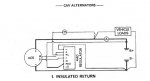
I have a 24v CAV alternator (AC5 or AC7 I think) for various reasons I disconnected it and can't find my notes to reconnect the alternator to the regulator. It looks fairly simple, there are two large black cables from the alternator , marked "B-" & "B+" which I presume go to the battery and two smaller red cables which need to connect to terminal "A" and terminal "F" on the regulator. The A&F are clearly marked on the regulator but I have no ideal which of the two red cables from the alternator are which.
My plan is to connect the battery cables start the engine without the two smaller cables connected and ideally, using a multi metre, measure something to establish which is which alternatively just a guess which way round they go and see what happens.
So my questions are
A) Will powering things up for a short period without these cables connected cause an issue.
B) What, if anything, can I measure with the multi metre.
C) Will I damage something if I get them the wrong way round ?
Thanks in advance for your advice.