3 phase Alternator Rectifier diodes

superheat6k

Well-known member
Joined
10 Jan 2012
Messages
6,762
Location
South Coast
Visit site
I have been re-wiring an engine with a built in 3 phase alternator.

The original 3 phase to DC rectifier assembly has been replaced so is not original. It is also in a terrible state, but I have found an identical Lucas replacement.

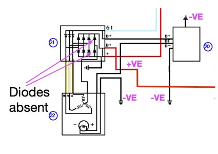
This rectifier omits two diodes which originally connected the Alternator winding star point to the DC output (see diagram) below.

1 Will the alternator work without the extra diode pair ?

I have been right through my 12 volt alternator manual and having this extra pair of diodes to a generator star point is not shown or mentioned anywhere.

Or

2 Should I connect in an extra pair of diodes to the DC output with the centre connection back to the presently unused star point terminal. This is labelled 'Y'.

If so can someone help me with the selection of a suitable pair of diodes. The alternator output is ~14v up to ~ 60 amps I would estimate. The current at the star point would be quite low. Indeed in theory it should be zero assuming the three fields windings are all equal, although there is some small variation in the individual field resistances (0.5 to 0.6 ohms).

I have checked the original wiring diagram for the specific engine and for several variants and all show this 4 pair set up of the main diodes.

Thanks.
 
Last edited:

neil_s

Well-known member
Joined
28 Oct 2002
Messages
1,629
Location
Chichester
Visit site
I can't see your diagram - but here's a thought. Are the diodes in parallel and connected with opposite polarity? If so they may be there to adjust the output voltage of the alternator.
 

habeer

New member
Joined
30 Mar 2009
Messages
23
Location
Michigan, USA
Visit site
I'm not an expert in three phase alternator rectifiers, but I have worked with three phase rectifiers. There should be three pairs of diodes, as it's basically a bridge rectifier and a half. (NB: My experience is with 7-10 kV 3-5A supplies, but the concept is the same)

Harold
 

rogerthebodger

Well-known member
Joined
3 Nov 2001
Messages
13,635
Visit site
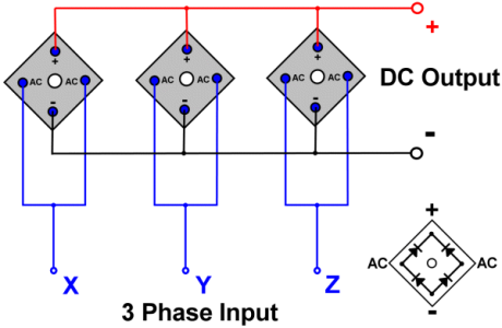
This is an alternative
OIP.EazMmy3ZAUqvIqQcUxjc7QHaES


THREE%2BPHASE%2BFULL%2BWAVE%2BUNCONTROLLED1.png
 

Alex_Blackwood

Well-known member
Joined
19 May 2003
Messages
1,885
Location
Fareham
Visit site
I have been re-wiring an engine with a built in 3 phase alternator.

The original 3 phase to DC rectifier assembly has been replaced so is not original. It is also in a terrible state, but I have found an identical Lucas replacement.

This rectifier omits two diodes which originally connected the Alternator winding star point to the DC output (see diagram) below.

1 Will the alternator work without the extra diode pair ?

I have been right through my 12 volt alternator manual and having this extra pair of diodes to a generator star point is not shown or mentioned anywhere.

Or

2 Should I connect in an extra pair of diodes to the DC output with the centre connection back the presently unused star point terminal.

If so can someone help me with the selection of a suitable pair of diodes. The alternator output is 14v up to ~ 60 amps I would estimate. The current at the star point would be quite low. Indeed in theory it should be zero assuming the three fields windings are all equal, although there is some small variation in the individual field resistances (0.5 to 0.6 ohms).

I have checked the original wiring diagram for the specific engine and for several variants and all show this 4 pair set up of the main diodes.

Thanks.
Your diagrams are not posted? However, If I understand from your last sentence that they were originally fitted, then they must be serving some purpose. Without more info. I would make a guess that they would be the same as fitted to the phase lines. Cannot say I have ever seen that arrangement before. But, everyday is a school day :unsure:
Really need the diagram.
Came across this , below, if it is what you had(have) then fit them. I would suggest. Won't do any harm.
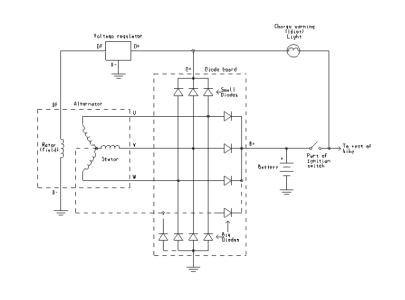
Why connect a 3-phase alternator's star-point to a rectifier bridge?
 
Last edited:

neil_s

Well-known member
Joined
28 Oct 2002
Messages
1,629
Location
Chichester
Visit site
I found this diagram - unfortunately, no explanation attached. Note, though, the reference to 'bike' on the right.
 

Attachments

  • alternator.png
    alternator.png
    24.8 KB · Views: 13

rogerthebodger

Well-known member
Joined
3 Nov 2001
Messages
13,635
Visit site
Your diagrams are not posted? However, If I understand from your last sentence that they were originally fitted, then they must be serving some purpose. Without more info. I would make a guess that they would be the same as fitted to the phase lines. Cannot say I have ever seen that arrangement before. But, everyday is a school day :unsure:
Really need the diagram.
Came across this , below, if it is what you had(have) then fit them. I would suggest.
Why connect a 3-phase alternator's star-point to a rectifier bridge?


Yes that is an interesting way of rectifying 3 phase basically rectifying 3 single phase connections which will result in a lower DC that as I posted

Can have an advantage if one of the phases is lost
 

superheat6k

Well-known member
Joined
10 Jan 2012
Messages
6,762
Location
South Coast
Visit site
Further to my previous. It won't hurt to omit them either 😵‍💫
Thanks, apart from the capacitor that is precisely what I should have. The reasoning makes sense if I were to lose one field coil. I will see if I can find a suitable diode as wiring them in will be very simple, and as part of the re-wire I have included a new star point cable back to the rectifier case.
 

William_H

Well-known member
Joined
28 Jul 2003
Messages
14,019
Location
West Australia
Visit site
I am quite confused
by this post. perhaps as a result of ignorance. As I understand most alternators have individual pressed in high current diodes. Three in to the body of the alternator and 3 in to a plate mounted inside the case and connected to positive output. (nB the diodes from each set are different in having anode to body or cathode to body)
I have not heard till now of diodes connected to the centre of the star. Though often the centre of the star has an output for tacho or in one car I had to heat an auto choke to release it.
I would imagine OP will find difficulty mounting the additional diodes anywhere on the alternator while providing a decent heat sink. External perhaps. But I would just omit them. Failure of a winding or of a diode I believe is uncommon now. (higher voltage rating of diodes) ol'will
 

superheat6k

Well-known member
Joined
10 Jan 2012
Messages
6,762
Location
South Coast
Visit site
I am quite confused
by this post. perhaps as a result of ignorance. As I understand most alternators have individual pressed in high current diodes. Three in to the body of the alternator and 3 in to a plate mounted inside the case and connected to positive output. (nB the diodes from each set are different in having anode to body or cathode to body)
I have not heard till now of diodes connected to the centre of the star. Though often the centre of the star has an output for tacho or in one car I had to heat an auto choke to release it.
I would imagine OP will find difficulty mounting the additional diodes anywhere on the alternator while providing a decent heat sink. External perhaps. But I would just omit them. Failure of a winding or of a diode I believe is uncommon now. (higher voltage rating of diodes) ol'will
On this engine the Rectifier is entirely separate from the Alternator and has 8 main diodes instead of the more normal 6. I am going to try it with the 6 diode Lucas rectifier as was already fitted. If not I have discovered today the original Bosch rectifier with the 8 main diodes is still available.

I would add I am possibly abusing the forum's technical knowledge base as this one is for a motorcycle alternator. All 12 volts and hence similar to a typical marine electrical issue. I did ask on the Owner's club, but nothing of any use for such a technical question.
 

Alex_Blackwood

Well-known member
Joined
19 May 2003
Messages
1,885
Location
Fareham
Visit site
On this engine the Rectifier is entirely separate from the Alternator and has 8 main diodes instead of the more normal 6. I am going to try it with the 6 diode Lucas rectifier as was already fitted. If not I have discovered today the original Bosch rectifier with the 8 main diodes is still available.

I would add I am possibly abusing the forum's technical knowledge base as this one is for a motorcycle alternator. All 12 volts and hence similar to a typical marine electrical issue. I did ask on the Owner's club, but nothing of any use for such a technical question.
Not at all, All grist to the mill, pleased to help if we can 😁 Think a lot of us learned from that post:unsure:
 

S04

Member
Joined
27 Jul 2024
Messages
49
Visit site
I'm not sure this is any help Alternator Secrets but it states:

"Newer alternators particularly high current models, use two additional diodes on the neutral connection to sample alternator output voltage for use by the regulator"

I can't comment on the validity of that claim but am just offering it for consideration.
 

superheat6k

Well-known member
Joined
10 Jan 2012
Messages
6,762
Location
South Coast
Visit site
I'm not sure this is any help Alternator Secrets but it states:

"Newer alternators particularly high current models, use two additional diodes on the neutral connection to sample alternator output voltage for use by the regulator"

I can't comment on the validity of that claim but am just offering it for consideration.
That's a very interesting read - thanks. In my case the star tap simply feeds to the +VE & -VE outputs via its pair of diodes. As in theory it should be neutral zero current will flow, so it will only contribute if the fields are out of balance. Even then I am not sure it will be too much.

The books I have read show the vast majority of car alternators are delta connected, so star connected are rare beasts indeed.

I have found the alternator DC output is rated to 20a, so at most the star circuit could never exceed this. I expect the Lucas rectifier I found fitted is from a car alternator so is likely capable of a far higher current than will be generated. I am going to look at using two of the diodes from the manky Lucas I have replaced as these will be of similar rating. Trying to size a diode requires at least a Masters degree or possibly a PHD in electronics ! Nothing like as simple as good old Ohm's Law.
 

William_H

Well-known member
Joined
28 Jul 2003
Messages
14,019
Location
West Australia
Visit site
That's a very interesting read - thanks. In my case the star tap simply feeds to the +VE & -VE outputs via its pair of diodes. As in theory it should be neutral zero current will flow, so it will only contribute if the fields are out of balance. Even then I am not sure it will be too much.

The books I have read show the vast majority of car alternators are delta connected, so star connected are rare beasts indeed.

I have found the alternator DC output is rated to 20a, so at most the star circuit could never exceed this. I expect the Lucas rectifier I found fitted is from a car alternator so is likely capable of a far higher current than will be generated. I am going to look at using two of the diodes from the manky Lucas I have replaced as these will be of similar rating. Trying to size a diode requires at least a Masters degree or possibly a PHD in electronics ! Nothing like as simple as good old Ohm's Law.
Ratings of silicon diode are fairly straight forward. You will see a rating of "Peak inverse voltage" this is the back wards voltage that if overloaded will destroy the diode. It will be hopefully 200 v or more. (more the better) Then there is the current rating. The more the better but current rating determines the body style and heat sink attachment arrangements. You would want at least 20 amp I would think.
Just looking at catalogues it seems the old single diode stud and plug type are not sold in hobby stores. The more popular bridge rectifier can be used just using sections needed. It looks like 400v PIV is common so no problems there. The bridge is bolted down to a large surface of aluminium or similar to dissipate heat.
ol'will
 

Alex_Blackwood

Well-known member
Joined
19 May 2003
Messages
1,885
Location
Fareham
Visit site
That's a very interesting read - thanks. In my case the star tap simply feeds to the +VE & -VE outputs via its pair of diodes. As in theory it should be neutral zero current will flow, so it will only contribute if the fields are out of balance. Even then I am not sure it will be too much.

The books I have read show the vast majority of car alternators are delta connected, so star connected are rare beasts indeed.

I have found the alternator DC output is rated to 20a, so at most the star circuit could never exceed this. I expect the Lucas rectifier I found fitted is from a car alternator so is likely capable of a far higher current than will be generated. I am going to look at using two of the diodes from the manky Lucas I have replaced as these will be of similar rating. Trying to size a diode requires at least a Masters degree or possibly a PHD in electronics ! Nothing like as simple as good old Ohm's Law.
Just a thought, as this is for a bike which, I suspect, may be worth a bit in itself, I would consider the Bosch original spare. Just to keep the spec. up.
 
Top