You are using an out of date browser. It may not display this or other websites correctly.
You should upgrade or use an alternative browser.
You should upgrade or use an alternative browser.
12v electrical advice
- Thread starter yourmomm
- Start date
VicS
Well-Known Member
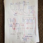
Let's get the discussion started. The topic has been up long enough with no replies
I dont think you will need to go quite as heavy as AWG 10 for the wiring between the solar panels and the controller. Unusual to include a circuit breaker
If you are going to use AWG 10 between the controller and the battery you must keep it very short ... total positive and negative less than 4m. I think I'd use heavier wiring here anyway because this is where volts loss will affect battery charging. The 10 amp circuit breaker is not big enough. You will hopefully get nearer 20 amps on a good day from 3 x 100 watt panels and an MPPT controller. id fit a fuse, close to the battery rather than a circuit breaker
You don't need to go as heavy as AWG 2/0 for circuits fused at 175 amps unless you have some very long cable runs
The fuse(s) in the VSR circuits must not be greater than the max current rating of the VSR ... I don't think you say what that is.
I don't like the dual circuit battery switch
I would fit 2 separate isolators AND an emergency crossover switch between the switched sides. Then you can isolate a duff battery and use just the good one via the crossover switch
To complete the isolation of a dud battery I think you will also need a switch in the VSR negative lead so that it can be disabled
My reply should prompt some others who disagree with my suggestions
If Paul Rainbow comes this way he will not like to use of AWG cable sizes
yourmomm
Well-Known Member
Yep thanks man.
Since posting elsewhere, I've learned:
1. Wire the panels in parallel not series, so would need to up both the solar CB sizes to 25A. The CB between panel and controller is just a switch, really, to allow work to be done involving a disconnect from batteries, without frying the controller. Happy to use a fuse instead of a CB from controller to batteries if it makes a difference? One dude told me to use a fuse on each end of that cable, which I've never heard of, before....
2. The run is indeed very short between mppt controller and batteries, but no worries going up another couple of cable sizes here....even more perhaps, for efficiency's sake.
3. Dont use a dvsr at all, as it will knacker my house batteries. Maybe use something like this instead:
Amazon.com: Xantrex Technology Inc, S-1591C, 82-0123-01 Digital Echo-Charge 15A: RADO AUTO
So solar and alternator can both be charging the house bank only, and this thing will do the rest...
4. Use 3x 175A terminal fuses, one on each of the house batteries' positive terminals, particularly in light of point 6, below.
5. Up the 175A terminal fuse on the starter circuit (still dont know what to, though, for a craftsman cm2.16 engine with 75A alternator; I mean I've got no idea how many amps it draws when it cranks; how do I calculate this?). So I'm just picking numbers out of thin air. 300A?
6. That my batteries which make up the house bank are too far apart from each other (each is 2m cable distance, from the next). But I can't do anything about this. The boat is only 25ft, and has about exactly the storage space you would expect in a 25ft boat. So I've had to settle on parallelling cables which are four gauges higher than I actually need (2/0), balance them, with positive feed on battery no. 1, and negative return on battery no. 3, and keep an eye on voltage drop under continuous high load (or charge), to see if its unacceptable; if it is, then better split the single house batteries bank, into separate banks.
7. That my use of AWG is offensive to many, and that I'd better sort this sort of behaviour right out. Oh, and also that I dont need anything like 2/0 for most of those cable runs. I've got the formula now for mm² calculations, and will aim for two sizes above minimums, instead.
8. Still have no idea whether the circuit actually works or not, mind you.
All other advice, greatdully received!
Last edited:
VicS
Well-Known Member
Yes you can wire the panels in parallel. Pros and cons of parallel vs series. I think I would go for parallel as that will probably be less affected by shading. AWG 10 will be suitable for the combined output of them in parallel.
I'd make the controller to battery wiring AWG 6, or AWG 8 if very short. The fuse needs to be at the battery end to protect the wiring from the large current which the battery could supply in the event of a fault. The purpose of a fuse at the controller end escapes me
I don't understand why you think a DVSR will be detrimental to your house battery bank
I know nothing about the Xantrex device . It's purpose seems to be to control / limit the charging of the engine start battery
An alternative scheme would be to use a Sterling "Alternator to battery" charger which will give enhanced charging of the house bank together with standard charging of the engine start battery.
I see your point about fitting fuses to each battery in the house bank but I think that if you cannot ensure that the interconnecting cables are secure and protected from harm you need fuses at each end.
If you are using AWG 00 for the starter battery connection you can increase the value of the fuse considerably ( AWG 00 is rated at 485 amps)
The circuit you posted will work.
yourmomm
Well-Known Member
Let's get the discussion started. The topic has been up long enough with no replies
I dont think you will need to go quite as heavy as AWG 10 for the wiring between the solar panels and the controller. Unusual to include a circuit breaker
If you are going to use AWG 10 between the controller and the battery you must keep it very short ... total positive and negative less than 4m. I think I'd use heavier wiring here anyway because this is where volts loss will affect battery charging. The 10 amp circuit breaker is not big enough. You will hopefully get nearer 20 amps on a good day from 3 x 100 watt panels and an MPPT controller. id fit a fuse, close to the battery rather than a circuit breaker
You don't need to go as heavy as AWG 2/0 for circuits fused at 175 amps unless you have some very long cable runs
The fuse(s) in the VSR circuits must not be greater than the max current rating of the VSR ... I don't think you say what that is.
I don't like the dual circuit battery switch
I would fit 2 separate isolators AND an emergency crossover switch between the switched sides. Then you can isolate a duff battery and use just the good one via the crossover switch
To complete the isolation of a dud battery I think you will also need a switch in the VSR negative lead so that it can be disabled
My reply should prompt some others who disagree with my suggestions
If Paul Rainbow comes this way he will not like to use of AWG cable sizes
Yes you can wire the panels in parallel. Pros and cons of parallel vs series. I think I would go for parallel as that will probably be less affected by shading. AWG 10 will be suitable for the combined output of them in parallel.
I'd make the controller to battery wiring AWG 6, or AWG 8 if very short. The fuse needs to be at the battery end to protect the wiring from the large current which the battery could supply in the event of a fault. The purpose of a fuse at the controller end escapes me
I don't understand why you think a DVSR will be detrimental to your house battery bank
I know nothing about the Xantrex device . It's purpose seems to be to control / limit the charging of the engine start battery
An alternative scheme would be to use a Sterling "Alternator to battery" charger which will give enhanced charging of the house bank together with standard charging of the engine start battery.
I see your point about fitting fuses to each battery in the house bank but I think that if you cannot ensure that the interconnecting cables are secure and protected from harm you need fuses at each end.
If you are using AWG 00 for the starter battery connection you can increase the value of the fuse considerably ( AWG 00 is rated at 485 amps)
The circuit you posted will work.
Thanks for this thoughtful response. Very helpful!
After feedback and consideration, I've adapted the original circuit to this (attached). I still have to work out cable sizes. Is this what you mean by "fuses at each end" of battery parallelling cables?
Thanks
Attachments
VicS
Well-Known Member
This how I would fit individual fuses to the house battery bank. Cube fuses would be ideal on the batteriesThanks for this thoughtful response. Very helpful!
After feedback and consideration, I've adapted the original circuit to this (attached). I still have to work out cable sizes. Is this what you mean by "fuses at each end" of battery parallelling cables?
Thanks
and how I would wire an emergency paralleling switch ( note, between the switched side of the battery isolators)


yourmomm
Well-Known Member
This how I would fit individual fuses to the house battery bank. Cube fuses would be ideal on the batteries
and how I would wire an emergency paralleling switch ( note, between the switched side of the battery isolators)
View attachment 85374View attachment 85375
So a 175A terminal fuse on each battery, (https://www.amazon.com/gp/aw/d/B07LC6PH1L/ref=ox_sc_act_image_6?smid=AMVRK92LFYKXB&psc=1) and an additional 175A fuse on the cable to the isolator?
VicS
Well-Known Member
If you don't have the additional fuse your common battery wiring and positive bus bar has 3 x 175 amps available to it in the event of a fault/ The alternative to the fuse would be to uprate the wiring, including the common negative wiring .
If you fit the emergency paralleling connection may find you have to increase the fuse rating if your starter moor draws more
If you fit the emergency paralleling connection may find you have to increase the fuse rating if your starter moor draws more
Gwylan
Well-Known Member
Have you decided fuses or breakers are there to protect the wiring or the components?
You might not need quite so many.
Why have the panels wired like that?
Stick them in parallel. With your arrangement any panel failure means total failure.
I prefer fuses not circuit breakers in this kind of use. Just a personal choice thing.
If it fails I have to respond and check, not just keep pushing the breaker. Also it limits the scope for jumping the fuse if necessary to get you home.
Agree isolators for each battery bank
Make up a jump lead for whenever you might need it. Means no visitors can fiddle! AMHIMKT?
Have a negative bus for everything to connect to. One big heavy wire joining all the negatives. Simplifies fault finding too.
What is the rationale for that way of wiring of the batteries to the solar panel and the alternator?
Why do you need a circuit breaker on the circuit breaker board? The individual breaker on an offending circuit should break before the 100A breaker. Not necessary, I think.
LadyInBed
Well-Known Member
Have you decided fuses or breakers are there to protect the wiring or the components?
You might not need quite so many.
Why have the panels wired like that?
Stick them in parallel. With your arrangement any panel failure means total failure.
I prefer fuses not circuit breakers in this kind of use. Just a personal choice thing.
If it fails I have to respond and check, not just keep pushing the breaker. Also it limits the scope for jumping the fuse if necessary to get you home.
Agree isolators for each battery bank
Make up a jump lead for whenever you might need it. Means no visitors can fiddle! AMHIMKT?
Have a negative bus for everything to connect to. One big heavy wire joining all the negatives. Simplifies fault finding too.
What is the rationale for that way of wiring of the batteries to the solar panel and the alternator?
Why do you need a circuit breaker on the circuit breaker board? The individual breaker on an offending circuit should break before the 100A breaker. Not necessary, I think.
Yes, I also think the 'system' is over protected.Have you decided fuses or breakers are there to protect the wiring or the components?
You might not need quite so many.
Why have the panels wired like that?
Stick them in parallel. With your arrangement any panel failure means total failure.
I prefer fuses not circuit breakers in this kind of use. Just a personal choice thing.
If it fails I have to respond and check, not just keep pushing the breaker. Also it limits the scope for jumping the fuse if necessary to get you home.
Agree isolators for each battery bank
Make up a jump lead for whenever you might need it. Means no visitors can fiddle! AMHIMKT?
Have a negative bus for everything to connect to. One big heavy wire joining all the negatives. Simplifies fault finding too.
What is the rationale for that way of wiring of the batteries to the solar panel and the alternator?
Why do you need a circuit breaker on the circuit breaker board? The individual breaker on an offending circuit should break before the 100A breaker. Not necessary, I think.
Remember that a circuit breaker can also be a point of failure!
yourmomm
Well-Known Member
Other threads that may be of interest
- Replies
- 5
- Views
- 317