Yanmar 6LP-STZE tachometer not working

Mission Control

New member
Joined
2 Jan 2023
Messages
3
Visit site
Hi
Could anyone please tell me the best way to troubleshoot this?

I have had an electrician on board but he wasn't able to determine where on the motor the sensor was.

Thanks in advance

Rodger
 

ChromeDome

Well-known member
Joined
25 Sep 2020
Messages
3,902
Location
Commonly in Denmark. Dizzy Too, most of the time.
Visit site
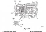
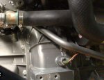
Not an owner myself, but a quick search shows that there should be a pickup on the flywheel housing.

I'd expect a boat mechanic or electrician to know:

y1.jpg

y4.jpg

y2.jpg
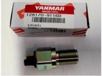
Yanmar OEM tach sensor for 1GM, 1GM10, 2GM, 2qm15, 2GMF, 2GM20, 2GM20F, 2GM20F-YEU, 2GM20-YEU, 3GM, 3GMF, 3GM30, 3GM30F, 3GM30F-YEU, 3GM30-YEU,4JHE, 4JH-TE, 4JH-HTE, 4JH-DTE, 6LP-DTE

Non OEM part may be available

y3.jpg
 
Last edited:

oldgit

Well-known member
Joined
6 Nov 2001
Messages
28,265
Location
Medway
Visit site
Have a Yanmar powered boat set up with a tacho both in the saloon and on the fly.
The fly tacho worked when it felt like it but the one in the saloon always functioned perfectly.
May not be the tacho itself but the assorted joints between sensor and instrument.
The fly tacho started to behave after some use, possibly due to simply being used !
There is a downloadable wiring diagram for the Yanmar and Yanmar with sourced dash online.
Wiring on my boat is a custom birds nest hybrid of Yanmar and Dufour.
 

Mission Control

New member
Joined
2 Jan 2023
Messages
3
Visit site
Have a Yanmar powered boat set up with a tacho both in the saloon and on the fly.
The fly tacho worked when it felt like it but the one in the saloon always functioned perfectly.
May not be the tacho itself but the assorted joints between sensor and instrument.
The fly tacho started to behave after some use, possibly due to simply being used !
There is a downloadable wiring diagram for the Yanmar and Yanmar with sourced dash online.
Wiring on my boat is a custom birds nest hybrid of Yanmar and Dufour.


The location of the sensor would be the first point to check for proper connections.
The sensor looks very much to be a Hall sensor so the accurate distance to the teeth on the flywheel (0.32-0.62) is crucial.

OTOH, it wouldn't be the first time a Hall sensor fails.
[/QUOTE]

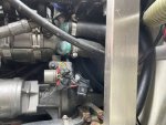
Ok - I have had a good look and feel around and pretty sure there is no sensor on the flywheel - (see photo)although it is pretty hard to get a good look is there any other place it could be?
 

Attachments

  • 24A9147C-AE12-4EAA-836A-CF4E6B270B12.jpeg
    24A9147C-AE12-4EAA-836A-CF4E6B270B12.jpeg
    447.5 KB · Views: 19

ChromeDome

Well-known member
Joined
25 Sep 2020
Messages
3,902
Location
Commonly in Denmark. Dizzy Too, most of the time.
Visit site
Surprising, Toyota (who made the base engine) are not known for changing a lot if they don't have to.
What year and serial no. is your engine?

Another site also shows the sensor so at least on some of these engines it should be there:
6lp_schematic.jpg

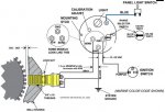
Even the diagram has it - the wire between the instrument and the sender should be orange and the ground should be black. I think I can see these two colours in you picture, near the black box?

There can be a number of multiconnectors in the harness.

6lpdiagr.jpg


Some engines use the alternator as the signal source (W terminal). Sometimes (e.g. on my Nannis) the wire is merged into the harness somewhere, not at the alternator.

If you clean all the connector(s) also on the alternator and ensure proper, firm, connection you may see the tacho come to live. Follow the wires and check for damage, clean all connectors.

I'd suggest spraying a dedicated contact cleaner on and a contact protector after refitting everything.

Earlier some tachos were clamped to a fuel line utilizing the sharp pulses every time the metal expands


Do you own any manuals for the engine?
 
Last edited:
Top