Wiring woes

PabloPicasso

Well-Known Member
Joined
12 Feb 2010
Messages
2,940
Visit site
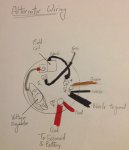
I'm still struggling to work out how to wire up my alternator. It's a Volvo penta 2001 engine, not sure what make the alternator is, I can't see a makers name on the casing

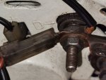
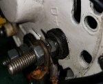
There is a brown wire, I think might go to the warning lamp and I cannot work out which terminal it connects to. There are terminals marked + and D- (as well as a W and a B+).

Electrics are not my forte. Anyone got a clue?image.jpeg
 
This manual shows layout of quite a few specific alternatirs.

D- is likely the negative main output and can connect to earth / ground
B- is normally the main power out + and will be a heavy connection
W- is normally the tacho pulse feed
+ - is normally the auxilary +, so likely where your brown wire goes.

12volt handbook.pdf
 
I'm still confused . The + in the pic appears to be for the black wire which leads to a small black box on the alternator casing. Leaving only D- for the brown wire. I have no confidence that this is correct .
 
I'm still confused . The + in the pic appears to be for the black wire which leads to a small black box on the alternator casing. Leaving only D- for the brown wire. I have no confidence that this is correct .
The two black wires go to the D- terminal. It should be obvious that this is a heavy terminal which is the main negative connection.

The brown wire goes to a terminal which may be labelled 61 or D+.( It is indeed the warming light connection)

The heavy red wire is the main positive output and should go to the other heavy terminal , probably labelled B+

The tachometer connection ( a grey wire) should go to the W terminal

Refer to the wiring diagrams in the owners manual

The 12 volt Doctors Alternator Book my be a better source of information than the 12 volt Doctors Handbook to which Superheats link directs you


Be aware that your engine has an isolated DC system. The engine block is not used as a common negative connection ( DC negative is only connected to the block by the earthing relay during starting) Take care not to compromise this isolation of the engine block or you may suffer from corrosion of your sail drive
 
Last edited:
Does this help? Does it look the same?
The blue wire & one of the red wires in the bottom left are for my independent hour meter so you can ignore those
Volvo MD 2020 alternator you can see what way up it is and work out what wires go where as a process of elimination perhaps
Somebody may come along & tell you which terminals are which on this picture
Alternator (600 x 576).jpg
 
Last edited:
Looks like a Prestolite alternator to me.

66021151M - Alternator Product Details | Prestolite / Leece-Neville

The "black box" is a capacitor, it is connected correctly.

The photo of the rear of the alternator terminals match what we see in your picture, but, don't match the drawing of the rear of the alternator. Unless, you accept that what looks like D- is actually D+

In your picture, there is a cable bolted to the D-/D+ terminal, where does this go ? Has it been off and you put it there ? What size is the nut on this terminal ?
Yes, it was a D+

It just didn't look that way from the obscured odd angled view through the hatch in the side panel

I feel a bit silly but better safe than sorry

Thanks again for everyone's help
 
Don't feel stupid and it's wise to ask if you don't know. I've asked lots of simple questions on this forum and had good advice - members are very happy to advise. It's what the forum is about
 
This manual shows layout of quite a few specific alternatirs.

D- is likely the negative main output and can connect to earth / ground
B- is normally the main power out + and will be a heavy connection
W- is normally the tacho pulse feed
+ - is normally the auxilary +, so likely where your brown wire goes.

12volt handbook.pdf

I guess there's a typo in the highlighted text above ?
 
Yes, it was a D+

It just didn't look that way from the obscured odd angled view through the hatch in the side panel

I feel a bit silly but better safe than sorry

Thanks again for everyone's help

I think your diagram is still wrong.

The black box is not a field coil, it's a capacitor, but it's connected correctly.

The B+ connections are correct.

That leaves three connections, the negative (B-), rev counter (W) and warning lamp (D+). If the alternator is the same as the one i posted details of, the rear diagram identifies the B-, D+ and W terminals. However, i didn't say that the terminal is D+, i'm questioning it. You need to answer the two questions in post #7
 
Yes I think I've got it sorted. Thanks all for your help.
I am sure that is not right

The brown is the warning light . It certainly should not be grounded ......... the light will always be on if it is and there will be no initial excitation to get the alternator to start generating

I think all the black wires should go to the same terminal, the one with the heavy negative connection on it. ( marked D - )

Once the capacitor negative wire is moved to the main negative terminal the spade poking through the back of the case will be free. That is were I am sure the brown wire should be connected.

Your diagram makes it all much clearer.
 
Last edited:
I am sure that is not right

The brown is the warning light . It certainly should not be grounded ......... the light will always be on if it is and there will be no initial excitation to get the alternator to start generating

If you connect it to a + terminal, as you suggest, it will never come on and there will still be no initial excitation.

I think all the black wires should go to the same terminal, the one with the heavy negative connection on it. ( marked D - )

Is that D- or D+ ? The Prestolite image of the rear of the alternator looks very much like D-, as does the OPs pic, but the schematic states it' D+

Once the capacitor negative wire is moved to the main negative terminal the spade poking through the back of the case will be free. That is were I am sure the brown wire should be connected.

Where to you get the idea that the wire is negative ? The Prestolite picture and diagram both show this wire is in the correct position.

Your diagram makes it all much clearer.

It's a sketch of the Prestolite image i posted, but it has the negative wires on the D+ terminal.

It would be very helpful if the OP revealed the answers to the two questions in post #7


Why would you connect the warning lamp to a positive terminal ?
 
I think two Black negative wires and the brown lamp wire must be right. I'll let you know how it turns out
 
Last edited:
Top