lustyd
Well-known member
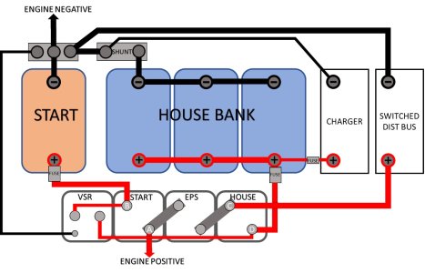
My charger just died and new one en route but the necessity of mucking about with wires got me thinking again about VSR and charging/discharging. Currently the VSR is set up to dual sense which means that when the MPPT charges the engine battery gets connected and drains alongside the house bank, which I think we can all agree is a bad thing. The reality is that with the various charge sources on board, while cruising the VSR is almost never disconnected.
So, current thinking (and I probably have not thought it all the way through!) is to change to single sensing and have the VSR sense wire on the engine side of the engine battery switch so that when the alternator is on it will activate and allow house bank charging. This also means that when the engine switch is off, the VSR can't join the batteries and the engine battery is safe.
I'm then thinking I can connect the trickle charge wires of the Phoenix IP43 1+1 to the battery side of this switch, and it'll trickle charge the engine battery while all switches are off.
On the house side, the MPPT is on the battery side of the switch, along with the VSR sense wire and I think the main charge cable. I think all of these need to stay battery side to ensure the battery gets charged regardless of the state of the switch, as well as to ensure the VSR doesn't activate in a scenario where the engine switch is on and house off, allowing engine battery to power house loads.
Obviously also have an emergency connect switch.
Does all that make sense? This would also seem to offer a better solution to allowing the charger to charge with an appropriate charge profile just for the house bank.


