Volvo Penta D2-50 engine rewiring

simon_ballantine

New member
Joined
27 Jul 2024
Messages
4
Visit site
The MDI black box on my 3 year old engine has failed again, this time 1,000 miles from home; so I am resolved to strip out all the electronic rubbish and relace it with a conventional instrument panel and switching...... cheaper and much more reliable than replacing the MDI unit again.
My understanding is that the early D2 engines had conventional controls before the MDI system was introduced. Can anyone please help me with a wiring diagram for an early D2 engine?
Specifically I want to know if I need relays for the starter/glowplugs - (the control panel and loom I am looking at has chunky wires, so I am assuming not.) Also if I put a 33ohm resistor in the alternator excite wire, do I connect this to the ignition terminal at the key so that is always on when the engine is running, or do I connect it to the Start terminal of the key so that it only sees voltage for a few seconds?
 

VicS

Well-known member
Joined
13 Jul 2002
Messages
48,521
Visit site
You will find wiring schematics in the workshop manual here :- https://j109.org/docs/volvo_d1-30_workshop_manual.pdf ( page 100 et seq )

You will see that the glow plugs and the starter are both controlled by relays ( this avoids the fairly high currents and the need for appropriately heavy wiring all the way to the control panel and back again)

You will also see that the excitation circuit via the resistor is energised all the time the key switch is in the normal running position . It will not be energised for long enough if fed from the start terminal.
 

simon_ballantine

New member
Joined
27 Jul 2024
Messages
4
Visit site
You will find wiring schematics in the workshop manual here :- https://j109.org/docs/volvo_d1-30_workshop_manual.pdf ( page 100 et seq )

You will see that the glow plugs and the starter are both controlled by relays ( this avoids the fairly high currents and the need for appropriately heavy wiring all the way to the control panel and back again)

You will also see that the excitation circuit via the resistor is energised all the time the key switch is in the normal running position . It will not be energised for long enough if fed from the start terminal.
Many thanks for taking the time to help me out. Thats a great help to me, Thanks.
 

Beneteau381

Well-known member
Joined
19 Nov 2019
Messages
2,087
Visit site
The MDI black box on my 3 year old engine has failed again, this time 1,000 miles from home; so I am resolved to strip out all the electronic rubbish and relace it with a conventional instrument panel and switching...... cheaper and much more reliable than replacing the MDI unit again.
My understanding is that the early D2 engines had conventional controls before the MDI system was introduced. Can anyone please help me with a wiring diagram for an early D2 engine?
Specifically I want to know if I need relays for the starter/glowplugs - (the control panel and loom I am looking at has chunky wires, so I am assuming not.) Also if I put a 33ohm resistor in the alternator excite wire, do I connect this to the ignition terminal at the key so that is always on when the engine is running, or do I connect it to the Start terminal of the key so that it only sees voltage for a few seconds?
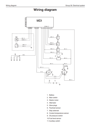
As I said in the other post, I have the wiring diagrams to fit a Beta marine panel. Quite simple really using Deutsch connectors
 

Beneteau381

Well-known member
Joined
19 Nov 2019
Messages
2,087
Visit site
You will find wiring schematics in the workshop manual here :- https://j109.org/docs/volvo_d1-30_workshop_manual.pdf ( page 100 et seq )

You will see that the glow plugs and the starter are both controlled by relays ( this avoids the fairly high currents and the need for appropriately heavy wiring all the way to the control panel and back again)

You will also see that the excitation circuit via the resistor is energised all the time the key switch is in the normal running position . It will not be energised for long enough if fed from the start terminal.
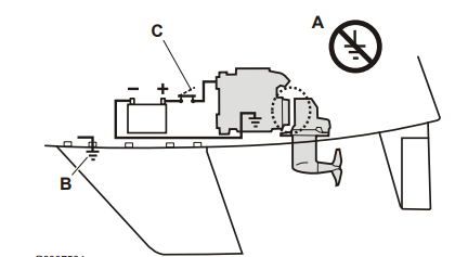
Just check that the relays are are also isolating the engine from negative earth? Like most VP engines they dont like the block to be earthed? IIRC
You will find wiring schematics in the workshop manual here :- https://j109.org/docs/volvo_d1-30_workshop_manual.pdf ( page 100 et seq )

You will see that the glow plugs and the starter are both controlled by relays ( this avoids the fairly high currents and the need for appropriately heavy wiring all the way to the control panel and back again)

You will also see that the excitation circuit via the resistor is energised all the time the key switch is in the normal running position . It will not be energised for long enough if fed from the start terminal.
I can see that this version is block negative ground. Check the MDI version, I’m sure it is negative isolated because iirc the oil pressure switch had to be changed to a two pin one, ie negative isolated.
 

VicS

Well-known member
Joined
13 Jul 2002
Messages
48,521
Visit site
Good points and something to double check but the wiring diagram in the workshop manual shows a negative grounded block system although most of the sensors are the two wire type ( overheat sensor being the obvious exception)

The little diagram in the owners manual also shows a negative grounded block (and an isolated saildrive where applicable)

1722280952980.png

1722281270089.png
 
Top