Triton2 problem

dgadee

Well-known member
Joined
13 Oct 2010
Messages
3,744
Visit site
Triton2 shows all the devices I have attached to network. just having added RPi MacArhtur Hat (via Signal K) and Standard Horizon gx2400 (AIS and GPS). However, it won't take data from these latter items. I know the data is on the network because my RPi is showing AIS info from the VHF.

What might be the problem?

Wind and depth are what I have now.
 

dgadee

Well-known member
Joined
13 Oct 2010
Messages
3,744
Visit site
Yes, went over a number of options - auto and manual selection. "Configure" shows the device but "data" doesn't show any data items. Those pages say, "The data option shows all date being output by the device." That is clearly not happening.
 

KompetentKrew

Well-known member
Joined
27 May 2018
Messages
2,359
Visit site
So both the RPi MacArhtur Hat and the Standard Horizon GX2400 are on the NMEA 2000 network?

Or does the GX2400 connect to the hat via 0183, expecting the hat to forward it?
 

dgadee

Well-known member
Joined
13 Oct 2010
Messages
3,744
Visit site
Everything connects onto the NMEA 2000 network. There are no connections except via that network.

I wondered about end resistors because the wind sensor might have a terminator built in. So checked resistance on the line before connecting to the Hat and it was 120k. I think the network is as it should be - power directly to it, everything with its own power supply (except the Triton2), and no drop cable to the new added devices more than 6m.
 

Martin_J

Well-known member
Joined
19 Apr 2006
Messages
4,340
Location
Portsmouth, UK
Visit site
120 ohm is the measurement you'd get across white/blue with just a single 120 ohm terminator at the end of the bus.

With the correct number i.e. with one at each end of the bus, you would expect to measure 60 ohms between blue and white.
 

dgadee

Well-known member
Joined
13 Oct 2010
Messages
3,744
Visit site
Ah! That may be the problem.

I will be down tomorrow and draw up a connection diagram. I am not sure how the mast wiring is arranged - will have to take a panel off to see if there is a box.
 

KompetentKrew

Well-known member
Joined
27 May 2018
Messages
2,359
Visit site
I'd disconnect the Pi to start with - check AIS data from the GX2400 can be shown on the Triton. Then add the Pi.
 

Martin_J

Well-known member
Joined
19 Apr 2006
Messages
4,340
Location
Portsmouth, UK
Visit site
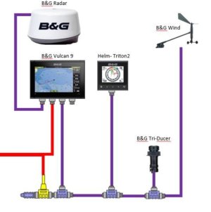
Two common types of mashead connection ..

First method with NMEA 2000 (purple) to the mashead and MHU (mast head unit) has to have a built in terminator..

Screenshot_20240712-090501_Samsung Internet.jpg


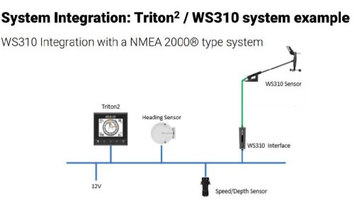
And a WS310 style of connection (shown in the second diagram) which has a connector into the NMEA2000 bus at or below deck level and non-NMEA2000 wiring up the mast...

The bus doesn't show the terminators but the NMEA2000 is the part in blue below.

The interface convertor isn't that big and to be honest, to some it just looks like a big NMEA2000 plug.

20240712_090554.jpg
 

dgadee

Well-known member
Joined
13 Oct 2010
Messages
3,744
Visit site
I'd disconnect the Pi to start with - check AIS data from the GX2400 can be shown on the Triton. Then add the Pi.
Pi was only added today. Prior to that the Triton didn't get the data from the GX2400. I thought the vhf was the problem, but when I added the pi to the network it picked up the AIS from the GX2400 showing that it was sending out data.
 

dgadee

Well-known member
Joined
13 Oct 2010
Messages
3,744
Visit site
Two common types of mashead connection ..

First method with NMEA 2000 (purple) to the mashead and MHU (mast head unit) has to have a built in terminator..

View attachment 181417


And a WS310 style of connection (shown in the second diagram) which has a connector into the NMEA2000 bus at or below deck level and non-NMEA2000 wiring up the mast...

The bus doesn't show the terminators but the NMEA2000 is the part in blue below.

The interface convertor isn't that big and to be honest, to some it just looks like a big NMEA2000 plug.

View attachment 181418
I think I am figure 1. Will check tomorrow.
 

Martin_J

Well-known member
Joined
19 Apr 2006
Messages
4,340
Location
Portsmouth, UK
Visit site
Remember that the calculation for resistance is due to any terminators on the backbone effectively being connected in parallel.

You should measure 60 ohms when resistance tested and there are the correct number (i.e. two) terminating resistors on the bus.

120 ohms would mean there is only 1 terminator, and 40 ohms or less would mean there are three or more terminators on the bus.

To test the resistance, the network power should be OFF, and the resistance measurement is done on the comms pair (Blue and White Wires).
 

Martin_J

Well-known member
Joined
19 Apr 2006
Messages
4,340
Location
Portsmouth, UK
Visit site
An incorrect number of terminators can produce all sorts of different/odd symptoms.

The most I have have found on a backbone whilst investigating issues was five. The main symptom had been that various instruments appeared to drop off the bus when the VHF was switched on!
 

dgadee

Well-known member
Joined
13 Oct 2010
Messages
3,744
Visit site
I am sorted! Resistance was 60 ohm so the network was fine. I updated the Triton software, played around with everything for a couple of hours and then - I think it was a setting on the GX2400 - position data appeared at the Triton. No idea what I did. OpenCPN was receiving AIS and gps without a problem so the data was clearly being sent.

I would like, though, an idiot's guide to Signal K. I also have no idea how that all works and integrates with OpenCPN and the network. Even a basic outline would be helpful. It seems to be a very effective piece of software when you have got over the initial confusion. Mind you, there is still more confusion in store for you even after that.
 
Top