nigelmercier
RIP
- Joined
- 20 Jun 2007
- Messages
- 16,234
- Location
- Live in Kent, boat in Canary Islands
I have now decided that I'm going to build a slope fronted box to flush mount my CP180 and [Matsutec HP-33A AIS Transponder]...
I've got two templates for mounting my CP180; one with two small holes, one with one large hole. I've made a composite below:

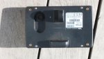
I can't decide how to cut this as I don't remember what the back of the CP180 looks like.
Has anybody got any pictures of the CP180 back, or can take a couple? If the latter, square on, fully zoomed in from a distance if possible.
[UPDATE] Picture sorted, thanks for the replies. New question about fitting screws.
Last edited: