Question about Navtex wiring

tymonk

Member
Joined
3 Sep 2022
Messages
54
Visit site
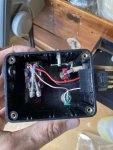
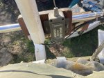
Hi. There is a Navtex in a second hand boat I purchased. The former owner (unfortunately deceased) has wired his Navtex up to a little switch box. 3 cables come out of the Navtex (red/black/orange, which I assume is +/-/ground) + the antenna cable. These wires go to their respective colour, and the orange one to the pink cable in the pictures. Next to the switch box are 4 wires: a positive and a negative, and 2 antenna cables. There are 2 Navtex antennas as the back. My assumption has been that the former owner wanted a way to both turn the Navtex on and off, and a way to switch between both antennas. However, it really confuses me that what I assume is the ground cable (pink wire in the picture) is linked to one of the switches, and why this connects to the red wire. I assume each antenna cable can be connected to the top/bottom of the of the antenna switch, and that the wire connecting it to the housing is the antenna ground? Apparently he was an electrical engineer and knew what he was doing.

If anybody can help decipher this and recommend on a way forward (potentially finishing this wiring project he started!) it would be much appreciated.
1 copy.jpgIMG_1995 copy.jpg
 

Plum

Well-known member
Joined
6 Jun 2001
Messages
4,534
Location
UK East Coast
Visit site
Hi. There is a Navtex in a second hand boat I purchased. The former owner (unfortunately deceased) has wired his Navtex up to a little switch box. 3 cables come out of the Navtex (red/black/orange, which I assume is +/-/ground) + the antenna cable. These wires go to their respective colour, and the orange one to the pink cable in the pictures. Next to the switch box are 4 wires: a positive and a negative, and 2 antenna cables. There are 2 Navtex antennas as the back. My assumption has been that the former owner wanted a way to both turn the Navtex on and off, and a way to switch between both antennas. However, it really confuses me that what I assume is the ground cable (pink wire in the picture) is linked to one of the switches, and why this connects to the red wire. I assume each antenna cable can be connected to the top/bottom of the of the antenna switch, and that the wire connecting it to the housing is the antenna ground? Apparently he was an electrical engineer and knew what he was doing.

If anybody can help decipher this and recommend on a way forward (potentially finishing this wiring project he started!) it would be much appreciated.

View attachment 142348View attachment 142349
If I were you I would dispense with the black box, check the installation instructions in the navtex manual and start wiring from scratch and use just the one aerial that you can identify as the original one that came with the navtex. No point in over complicating a navtex installation. On mine I also have a wire that supplies gps position data, via nmea, but not essential.

Www.solocoastalsailing.co.uk
 

tymonk

Member
Joined
3 Sep 2022
Messages
54
Visit site
If I were you I would dispense with the black box, check the installation instructions in the navtex manual and start wiring from scratch and use just the one aerial that you can identify as the original one that came with the navtex. No point in over complicating a navtex installation. On mine I also have a wire that supplies gps position data, via nmea, but not essential.

Www.solocoastalsailing.co.uk

Thank you. The unit is the Navtex Target Pro (not Pro-Plus) model. The instructions (https://www.nasamarine.com/wp-content/uploads/2016/08/Target-Navtex-Pro.pdf) don't mention anything about a third orange wire, though? Any idea about this?
 

Plum

Well-known member
Joined
6 Jun 2001
Messages
4,534
Location
UK East Coast
Visit site

Schuss39

Member
Joined
25 Nov 2009
Messages
70
Location
Plymouth, Devon
Visit site
I fitted one of the original Navtex Pro's to my then yacht, a Moody 31, back in 1997/8 era. It was originally only designed to receive Navtex on the 518khz frequency. The antenna was similar to that on the Left on your second photo tuned to the 518khz frequency.

Nasa then introduced an updated antenna (simular to that on the Right of your 2nd photo) when the 490khz frequency transmissions started a few years later. It had a two way switch, you moved it one way when you wanted to receive navtex on the 518 frequency and to the other way when you wanted the 490 frequency.

It was a simple by pass filter for the antenna tuned one way at 518 kHz and 490 kHz the other way. To my understanding it was not a power supply to the antenna. You could not receive both navtex frequencies at the same time. You had to use the switch to select what you wanted to receive.

When I fitted the updated updated antenna I removed the original 518khz one. The screen on my Pro failed around 2006/7 so I removed it completely. Replaced it with the ICS Nav6+.

Hope this helps.
 

tymonk

Member
Joined
3 Sep 2022
Messages
54
Visit site
I fitted one of the original Navtex Pro's to my then yacht, a Moody 31, back in 1997/8 era. It was originally only designed to receive Navtex on the 518khz frequency. The antenna was similar to that on the Left on your second photo tuned to the 518khz frequency.

Nasa then introduced an updated antenna (simular to that on the Right of your 2nd photo) when the 490khz frequency transmissions started a few years later. It had a two way switch, you moved it one way when you wanted to receive navtex on the 518 frequency and to the other way when you wanted the 490 frequency.

It was a simple by pass filter for the antenna tuned one way at 518 kHz and 490 kHz the other way. To my understanding it was not a power supply to the antenna. You could not receive both navtex frequencies at the same time. You had to use the switch to select what you wanted to receive.

When I fitted the updated updated antenna I removed the original 518khz one. The screen on my Pro failed around 2006/7 so I removed it completely. Replaced it with the ICS Nav6+.

Hope this helps.

Thanks for your response. There was a switch on the antenna, you mean? I'll have a double check and see if I can date where the antennas are from. What you say supports the theory that the previous owner wanted to switch between the 2 antennas.

Well worth considering changing to their H Vector Antenna if appropriate.

Thanks. I will check if this is the original Pro or the V2 (H-vector apparently only compatible with the latter. Would you know if the H-Vector receives at both frequencies?

Maybe still worth installing a little on and off switch so it's not always on when the battery is. And any definitive answer on the orange wire would still be most welcome.
 

Schuss39

Member
Joined
25 Nov 2009
Messages
70
Location
Plymouth, Devon
Visit site
I had no switch on the antenna or the mounting box. The small two way switch was about 75cm from the plug which pushed into the antenna socket of the Navtex Pro.

On my earlier post I got the two antennas the wrong way around. In your photo the one on the right was my original antenna, 518khz only. The wire wip was always getting broken & replaced with a suitable cut to length wire coat hanger.The one on the left, stubby, was the dual 518 & 490 kHz antenna which had the small two way switch in the antenna cable.

I did not use both antennas in my set up. It looks like your previous owner had his own modifications!! He may have set it up to receive both transmission frequencies without having to physically switch between the transmissions. Hence both antennas included with the additional box of circuitry he added. Hope this helps.
 

tymonk

Member
Joined
3 Sep 2022
Messages
54
Visit site
Thanks again for your reply. In a very old terrible quality manual (http://equinoxe.2.pagesperso-orange.fr/Doc/nasa-navtex.pdf) I did find this mention of the orange wire being for the backlight, which explains why the previous owner had connected this via a switch to the positive wire (although you're also meant to be able to turn it on and off via
the ENTER button ?‍♂️)

Screenshot 2022-09-07 at 11.50.01.png

I can't really find any proper documentation on any previous models to find out if this one can receive both frequencies... but I assume if there is no internal functionality to switch then there is no point in getting a fancy H vector antenna.
 

Pye_End

Well-known member
Joined
5 Feb 2006
Messages
5,145
Location
N Kent Coast
Visit site
Thanks. I will check if this is the original Pro or the V2 (H-vector apparently only compatible with the latter. Would you know if the H-Vector receives at both frequencies?

Seems to. I use it on their dual frequency android based set up. Switches between on a software timer. Good reception on both.
 

tymonk

Member
Joined
3 Sep 2022
Messages
54
Visit site
Seems to. I use it on their dual frequency android based set up. Switches between on a software timer. Good reception on both.

This may actually be the best/cheapest solution. Seems to be cheaper than any unit, even second hand.
 

Schuss39

Member
Joined
25 Nov 2009
Messages
70
Location
Plymouth, Devon
Visit site
That document looks very similar to the one I had years ago. Nassa were renowned for brief instruction manuals back then. Agree that the supply +12 volts was the red colour wire and black the earth. I don't think I used the orange back light one. Don't forget the fuse in +12v line.

Why not wire it up and see if you can set the stations and message types up. Then see if you receive anything from the two antennas.
 
Last edited:
Top