Perkins 4 236 Ignition Problems

Saiwana

New member
Joined
1 Jul 2022
Messages
5
Visit site
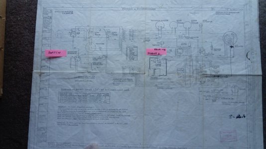
I have an Apollo 32 with a Perkins 4 236M circa 1975. Can anyone give me advice/ wiring diagram on the ignition system? I am not getting a voltage (12v) at the starter coil terminals (on the starter motor) when operating the ignition switch. Am trying to work out what all of the relays in a box next to the engine are for???? Batteries are fully charged and in good order.
Can anyone help?
 

PCUK

Well-known member
Joined
29 Jun 2005
Messages
8,000
Location
Westleigh, Nr Tiverton, Devon.
Visit site
There is no ignition circuit as such on a diesel, you are referring to the start circuit. This is very simple and consists of a solenoid, (heavy duty relay) which is operated by power from the start switch. You can test the starter motor by running a jump lead from the battery positive to the starter positive. Just touch it on the starter terminal for a few seconds and the starter should spin. If it doesn"t the problem is the starter. If it spins OK then do the same test on the solenoid positive terminal, if the starter spins then the problem is the wiring between the start switch and the solenoid. Good luck!
 

Tremyporth

New member
Joined
27 Sep 2021
Messages
22
Visit site
I have a 4.236 which had a similar problem. It was caused by a broken spade connector. The advice from PCUK is partially correct, but many diesel engines do in fact have ignition switches to activate the start circuit. Mine is one such. I know it is an ignition switch because the parts list for the Austin 1300 from which it came describes it as an ignition switch. Secondly, as you will have seen from looking inside the relay box, the circuitry is far from obvious or "very simple". Mine has three relays. One of the smaller ones is for the thermostart, the other for the alternator. The main starter relay is a larger Lucas SRB 341. If that is replaced with the similar looking SRB 335 it will not work because the internal circuitry is different. The live feed from the battery goes to the upper terminal on the relay, from which a sort of Christmas tree of wires fans out to other places. The thin brown one goes to the ignition or starter switch, and the return from switch to activate the relay is white and red. I have attempted to photograph my circuit diagram, but there were many versions of this engine so it may not be exactly the same as yours.
 

Attachments

  • 4.236 wiring.jpg
    4.236 wiring.jpg
    1 MB · Views: 5

Saiwana

New member
Joined
1 Jul 2022
Messages
5
Visit site
There is no ignition circuit as such on a diesel, you are referring to the start circuit. This is very simple and consists of a solenoid, (heavy duty relay) which is operated by power from the start switch. You can test the starter motor by running a jump lead from the battery positive to the starter positive. Just touch it on the starter terminal for a few seconds and the starter should spin. If it doesn"t the problem is the starter. If it spins OK then do the same test on the solenoid positive terminal, if the starter spins then the problem is the wiring between the start switch and the solenoid. Good luck!
Hi PCUK,
Thank you so much for your advice. A lot of good tips which has helped me find and repair the fault.
 

Saiwana

New member
Joined
1 Jul 2022
Messages
5
Visit site
I have a 4.236 which had a similar problem. It was caused by a broken spade connector. The advice from PCUK is partially correct, but many diesel engines do in fact have ignition switches to activate the start circuit. Mine is one such. I know it is an ignition switch because the parts list for the Austin 1300 from which it came describes it as an ignition switch. Secondly, as you will have seen from looking inside the relay box, the circuitry is far from obvious or "very simple". Mine has three relays. One of the smaller ones is for the thermostart, the other for the alternator. The main starter relay is a larger Lucas SRB 341. If that is replaced with the similar looking SRB 335 it will not work because the internal circuitry is different. The live feed from the battery goes to the upper terminal on the relay, from which a sort of Christmas tree of wires fans out to other places. The thin brown one goes to the ignition or starter switch, and the return from switch to activate the relay is white and red. I have attempted to photograph my circuit diagram, but there were many versions of this engine so it may not be exactly the same as yours.
Hi Tremyporth,

Thank you very much for the information and drawing. I have identified all of the parts you have mentioned. My initial thoughts were directed at the relays but when tracing the wiring I came across a badly corroded ferrule which was causing a significant volt. Terminal remade and all is well now. Your circuit diagram is excellent. Thank you.
 

Tremyporth

New member
Joined
27 Sep 2021
Messages
22
Visit site
Hi Saiwana. You are welcome. I recall it was a very strange sensation after a couple of hours fishing to press the start button and- nothing happened. After the initial patch up with a jumper lead to get home, and bearing in mind the age of the engine and installation, I concluded there might be other wires and connectors just waiting to fail in similar fashion. So by way of preventative maintenance I replaced most of the other connectors and some wiring in the starter circuit. Also installed a second live feed wire to the starter relay/ solenoid to provide "redundancy". Painting the terminals with Waxoyl seems to help reduce future corrosion. For peace of mind, you might like to consider doing something similar.
 
Top