YachtGannet
New Member
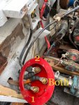
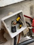
Hi, first time yacht owner of an Invicta 26 that suffers alternator problems. The alternator’s new, and I’ve stuck an even newer regulator on it. Ignition light goes on with key in position 1 then off when engine fires but I’m only getting battery voltage (currently 12.3ish) on both batteries and on the alternator itself. Battery connections have been cleaned up and tightened and all earths seem to be fine, so I thought I’d take a look at the back of the isolator switch to see how it had been wired. Does the attached look correct? Up until now I’ve always had this on the “Both” position when testing. The wires on the “2” position all go to the waterproof box adjacent to the isolator which I think is a shared positive - from that box the red lead goes up to the ignition panel and the brown lead with the yellow sleeve (I think, based on the cable gauge - it’s part of a heavily taped bundle that heads off to the starter solenoid) is the other end of the alternators B+. Does the “1,2,Both” isolator switch wiring look right?