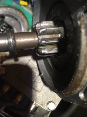
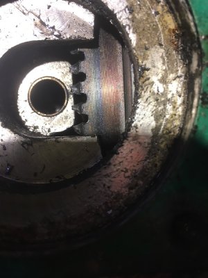
Farymann starter

Graham_Wright

Well-known member
Joined
30 Dec 2002
Messages
7,721
Location
Gloucestershire
www.mastaclimba.com
The flywheel starter ring on my Fischer Panda is badly damaged and no longer serves to start the generator. I bought the genny for £800 with a declared fault which I have fixed.
(Perhaps the ring was damaged during repeated attempts to start the engine with too little battery power.)
For a little over the original purchase price, Fischer Panda can supply a new ring (just the ring) and a replacement starter motor (dog not available).
Ouch!
Fortunately, I have sourced a complete flywheel with a usable ring for considerably less.
The existing starter dog looks usable although I will try to source a replacement.
My question relates to the operating philosophy of the starter motor.
It is a pre-engaged type but the spindle turns, motor driven, during the throw-out. Is this normal? Is this to ensure that the unlikely but theoretically possible tooth to tooth collision is avoided?
Further investigation, reveals that, during throw-out the solenoid coil and the motor windings are in a series. This results in a fairly half-hearted rotation.
The solenoid contacts appear to be made at the limit of the throw-out.
The flywheel teeth are axial rather than radial which is a new one for me.


eIMG_1866.jpgIMG_1864.jpgIMG_1865.jpg
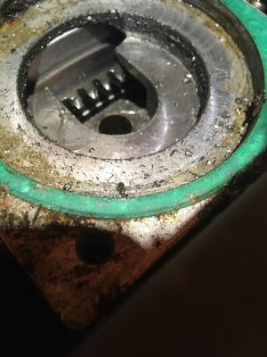
 
Last edited:

Graham_Wright

Well-known member
Joined
30 Dec 2002
Messages
7,721
Location
Gloucestershire
www.mastaclimba.com
You could build up the teeth with weld then grind back to profile both the starter dog and flywheel.
I believe that possible with the starter dog but for the ring, grinding to a reasonable profile would be a challenge!
I have hard metal sticks but TIG would be my preference and I don't know if standard TIG rods would be hard enough.
A new starter is around £200 but it is a shame as only the dog needs replacing.
 

ean_p

Well-known member
Joined
28 Dec 2001
Messages
3,012
Location
Humber
Visit site
I'm not familiar with your particular engine/ generator so bear this in mind with the following.
Ordinarily the pinion meshes with the aid of a leading edge applied to the teeth of both the pinion and the flywheel teeth. In addition there is a 'slight' revolving of the pinion shaft ( not the armature shaft as the two are often not the same, the former being driven by a small planetary gearbox which is driven by the armature shaft) induced by a spiral spline on the pinion shaft which operates in conjunction with the ratchet built into the thrust bearing assembly and the mount for the plant gears as well as the fork which applies the thrust from the solenoid. All this ensures that the pinion engages with the flywheel with the minimum of friction / collision. The starter shouldn't ordinarily be energised until the solenoid has completed its travel and the contacts within are made ( by which time the pinion is / should be fully engaged.) Again ordinarily the coil of the solenoid and the windings of the starter coils are in parallel rather than series I believe.
All the teeth on every flywheel I have seen have been 'axial' in that they are cut on the outside of the peripheral edge of the wheel and not 'radial' wherein I would expect them to be on either of the front or back face of the wheel.
Don't waste your time or effort trying to rebuild the damaged teeth of either the pinion or the flywheel as it will be doomed to failure unless you have access to a reasonable level of skill in metalworking and machining. At best you might gingerly clean up the existing teeth with a smooth file to remove some of the bruising they have suffered. The teeth on all are likely to be case hardened in that they have a hard skin on top of a softer core. If the core is exposed then the teeth are doomed. Normal wear shows as 'fretting' on the working face of the tooth and appears as a dark line like a dark flaky scratch that runs across the tooth in an otherwise shiny surface. Such fretting is the end of the tooth / gear approaching.
Was the damage on the old flywheel equal on all the teeth around the edge or was it just located in three or four areas around the edge?
If the former then it was most likely caused by a damaged pinion ( which your still using!) and if the latter then most likely by poor engagement meshing. Ensure that the movement of the pinion engagement is all good, smooth and free.
 

penfold

Well-known member
Joined
25 Aug 2003
Messages
7,733
Location
On the Clyde
Visit site
That is how pre-engage starters work; the weak rotation combined with the wedge cut in the teeth of the pinion helps it line up with the ring gear. It's a while since I looked at one but IIRC bendix inertia starters have wedges cut on the pinion teeth for the same reason.
 

rotrax

Well-known member
Joined
17 Dec 2010
Messages
15,495
Location
South Oxon, Littlehampton and Wellington, NZ.
Visit site
I'm not familiar with your particular engine/ generator so bear this in mind with the following.
Ordinarily the pinion meshes with the aid of a leading edge applied to the teeth of both the pinion and the flywheel teeth. In addition there is a 'slight' revolving of the pinion shaft ( not the armature shaft as the two are often not the same, the former being driven by a small planetary gearbox which is driven by the armature shaft) induced by a spiral spline on the pinion shaft which operates in conjunction with the ratchet built into the thrust bearing assembly and the mount for the plant gears as well as the fork which applies the thrust from the solenoid. All this ensures that the pinion engages with the flywheel with the minimum of friction / collision. The starter shouldn't ordinarily be energised until the solenoid has completed its travel and the contacts within are made ( by which time the pinion is / should be fully engaged.) Again ordinarily the coil of the solenoid and the windings of the starter coils are in parallel rather than series I believe.
All the teeth on every flywheel I have seen have been 'axial' in that they are cut on the outside of the peripheral edge of the wheel and not 'radial' wherein I would expect them to be on either of the front or back face of the wheel.
Don't waste your time or effort trying to rebuild the damaged teeth of either the pinion or the flywheel as it will be doomed to failure unless you have access to a reasonable level of skill in metalworking and machining. At best you might gingerly clean up the existing teeth with a smooth file to remove some of the bruising they have suffered. The teeth on all are likely to be case hardened in that they have a hard skin on top of a softer core. If the core is exposed then the teeth are doomed. Normal wear shows as 'fretting' on the working face of the tooth and appears as a dark line like a dark flaky scratch that runs across the tooth in an otherwise shiny surface. Such fretting is the end of the tooth / gear approaching.
Was the damage on the old flywheel equal on all the teeth around the edge or was it just located in three or four areas around the edge?
If the former then it was most likely caused by a damaged pinion ( which your still using!) and if the latter then most likely by poor engagement meshing. Ensure that the movement of the pinion engagement is all good, smooth and free.

When parts are unobtainable, a situation I came across many times in my business as a Veteran, Vintage and Classic bike restorer, measures must be taken to get the machine working again.

I wish some of my successful 'repairs' could have been as simple as welding and reshaping a starter gear and ring gear.

I welded and shaped by lathe and hand 11 teeth out of 16 on a 1930 Rudge worm drive oil pump spindle. The missing teeth were welded with a No.2 jet, 1/16th welding rod and Oxy-Acetylene.

After welding the spindle-about 3/4 inch diameter- was chucked and turned to diameter. This showed a couple of low spots that were 'touched up' and the process repeated. The slots were cleaned by locking the work in the chuck and winding, by hand, the toolpost forward with a hand ground bit of tool steel shaped as neccessary. This operation was carried out until the spindle meshed nicely with the crankshaft worm.

Very time consuming, but the job was a success, the bike still working AFAIK.

I am NOT an engineer, but a pretty handy mechanic. The welding - and subsequent hardening of the teeth - was easy for me. I was shown how to use the lathe by 'Speedo Ken' who was a clock and watch maker. He had been I/C the instrument section at AWRE Aldermaston. That ourageously clever man Alan Millyard was Kens apprentice.....................................
 
Top